SPECIFICATIONS
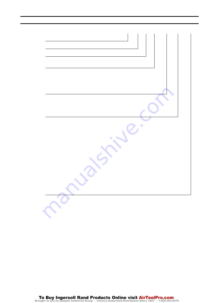
Model Code Explanation:
Example: FA150KGiMR12–1–C-E
FA
150KGi
MR
12
-
1
-
C
-
E
Series:
FA
= Force 5 Infinity Air Powered
Capacity (based on wire rope at full drum):
150KGi
= 330 lb [150 kg] Man Rider Rating
Man Rider
Designation:
MR
= Man Rider
Drum Length:
8
= 8 inches (203 mm)
12
= 12 inches (305 mm) (standard)
16
= 16 inches (406 mm)
24
= 24 inches (610 mm)
Drum Brake:
Manual Drum Band Brake Standard
A
= Automatic drum band brake
Control:
1
= Winch mounted lever throttle (Standard)
3XX
= Remote control (Contact factory) †
Wire Rope Take-off Range:
0°- 90°
Wire rope take-off angle (standard).
Contact factory for non-standard wire rope angles.
Design Temperature:
Blank
= 0° C (32° F) or warmer
C
= -20° C (-4° F)
Options:
7
= Grooved drum (Wire rope sizes in sixteenths, e.g. 7/16 in)
B
= Winch mounted base
E
= Emergency lowering system
F
= Air Line Accessories (mounted on front or back of winch guard panel)
H
= Stainless Steel Hoses (rubber hose is standard)
J
= Air Line Accessories
K
= Stowage valve
M1
= Typical Material Certificates (2.2) *
M2
= As-received traceability *
M3
= As-shipped traceability *
N1
= Type approval – ABS ††
N2
= Type approval – DNV ††
Q
= Special Paint ††
W1
= ABS – witness testing ††
W2
= DNV – witness testing ††
W3
= LRS – witness testing ††
W4
= Customer witness testing ††
X
= Testing ††
-E
=
Compliance with EU Machinery Directive, refer to “DECLARATION OF CONFORMITY” on page 15 (Includes emergency stop and overload
protection)
Notes:
* Refer to ‘Traceability’ on page 4 for a description of the differences between M1, M2 and M3.
† Not covered in this manual.
†† If N, Q, W or X are entered, the details must be specified in the text of the sales order.
Form MHD56314 Edition 4
3


