26
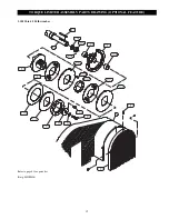
14. Using a straight edge, position sprocket (5) so it aligns with
the sprocket on drum (2). Install setscrews (32) with
Loctite
®
609 or equivalent and tighten.
15. Install chain (6) and adjust to obtain the correct chain
tension. It may be necessary to use a chain half link (37).
16. Install guard (3) on frame (1) and secure with capscrews
(15). Also install screws (16), washers (18) and nuts (24)
which clamp the guard mesh to the inside of the frame (1).
17. Check all warning labels and tags are present and clearly
visible.
Winch Assembly
15,000 - 25,000 lb winches
Refer to Drawings MHP0255 and MHP0278.
1.
Position frame (1) on a flat and sturdy surface.
2.
Wipe clean and lightly lubricate bearing spigots on the
drum (2). Install one bearing (39) on each drum spigot.
3.
Using an overhead hoist with sufficient capacity to
adequately support the weight of the drum (2) position the
drum in frame (1). Ensure bearings (39) are located on the
bearing pads of the frame (1).
4.
Align the bearing (39) mounting holes with the bolt holes
in frame (1). Loosely install capscrews (41), washers (42),
lockwashers (48) and nuts (43).
5.
Loosely install adjusting screws (11) with nuts (20) in
frame (1).
6.
Install bearing (40) on reducer assembly output shaft. Using
an overhead hoist with sufficient capacity to adequately
support the weight of the motor and reducer assembly
position the motor and reducer assembly on frame (1).
Install capscrews (17), washers (12), lockwashers (21) and
nuts (22). Install capscrews (17) from underneath the frame
(1). Torque to specifications recommended in torque chart.
7.
Align holes in bearing (40) and frame (1) and install
capscrews (45), lockwashers (46) and nuts (47). Torque to
specifications recommended in torque chart.
8.
Install key (31) and sprocket (5) on output shaft of motor
and reducer assembly (26) or (27).
NOTICE
• Do not force sprocket onto output shaft by hammering.
Doing so may cause premature bearing failure.
9.
Using a straight edge, position sprocket (5) so it aligns with
the sprocket on drum (2). Install setscrews (32) with
Loctite
®
609 or equivalent and tighten.
10. Install chain (6) with master link (37) to obtain the correct
chain tension it may be necessary to use a chain half link (37).
11. Install guard (3) on frame (1) and secure with capscrews
(15). Also install screws (16), washers (18) and nuts (24)
which clamp the guard mesh to the inside of the frame (1).
12. Check all warning labels and tags are clearly visible.
Winch Assembly (direct drive winches)
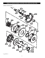
Refer to Drawing MHP0260.
1.
Wipe clean and lightly lubricate spigots on the drum (51).
Install key (55) on reducer assembly drive shaft and
assemble drum (51).
2.
Install capscrews (57) and washers (61) in frame (50). Slide
motor and reducer assembly with drum into position.
Spigot of drum must pass through the frame upright.
3.
Install bearing (58) and secure in position with lockwashers
(59) and nuts (60).
4.
Install capscrews (56) from underneath frame (50). Install
nuts (53) and washers (54) on capscrews (56) and torque to
specifications.
Repair
Actual repairs are limited to the removal of small burrs and
other minor surface imperfections from sprockets and shafts.
Use a fine stone or emery cloth for this work.
1.
Worn or damaged parts must be replaced. Refer to the
applicable Parts Listing for specific replacement parts
information.
2.
Inspect all remaining parts for evidence of damage. Replace
or repair any part which is in questionable condition. The
cost of the part is often minor in comparison with the cost
of redoing the job.
3.
Smooth out all nicks, burrs, or galled spots on shafts, bores,
pins, or bearings.
4.
Examine all sprocket teeth carefully, and remove nicks or burrs.
5.
Polish the edges of all shaft shoulders to remove small
nicks which may have been caused during handling.
6.
Remove all nicks and burrs caused by lockwashers.
Winch Assembly (chain driven winches)
Refer to Drawing MHP0255.
1.
Position frame (1) on a flat and sturdy surface or
workbench.
2.
Wipe clean and lightly lubricate bearing spigots on the
drum (2). Install one bearing (7) on each drum spigot. The
flat mounting surface of each bearing (7) must be toward
the drum (2).
3.
Loosely install the bolt locks (4) in frame (1) so they are in
a vertical position and are located on the chain side of the
frame (1). Bolt locks (4) must be positioned with the
narrower edge located closest to the ‘U’ shaped cutout in
the frame (1).
4.
Loosely install capscrews (14) in frame (1) on the side
opposite the chain.
5.
Using an overhead hoist with sufficient capacity to
adequately support the weight of the drum (2) position the
drum in frame (1). Ensure that bearings (7) are located on
the outside of the frame drum support uprights and that the
bearing grease fittings are positioned at the bottom.
6.
Align the bearing mounting holes with bolts (14) or bolt
locks (4) and press into position.
7.
Install nuts (19) and lockwashers (13). Torque to
specifications recommended in torque chart.
8.
Loosely install adjusting screws (11) with nuts (20) in
frame (1).
9.
Install caps (8) on top of each frame (1) support. Check
threaded hole in cap is positioned nearest the drum (2).
10. Install capscrews (9) and lockwashers (25) to clamp caps
into position. Torque to specifications recommended in
torque chart.
11. Loosely install adjusting capscrews (10) with nuts (20) in
caps (8).
12. Using an overhead hoist with sufficient capacity to
adequately support the weight of the motor and reducer
assembly position the motor and reducer assembly on
frame (1). Install capscrews (17), washers (12),
lockwashers (21) and nuts (22). Install capscrews (17) from
underneath the frame (1). Torque to specifications
recommended in torque chart.
13. Install key (31) and sprocket (5) on output shaft of motor
and reducer assembly (26) or (27).
NOTICE
• Do not force sprocket onto output shaft by hammering.
Doing so may cause premature bearing failure.
Summary of Contents for 10000B20
Page 13: ...12 DRUM SWITCH CONNECTION DIAGRAMS Dwg MHP0201...
Page 14: ...13 230 Volt Single Phase 60 Hz Dwg MHP0271 WIRING DIAGRAM...
Page 15: ...14 WIRING DIAGRAMS Dwg MHP1086...
Page 16: ...15 Dwg MHP1087 WIRING DIAGRAM 208 575 Volt Three Phase 50 or 60 Hz 22 Amp and smaller...
Page 17: ...16 WIRING DIAGRAM Dwg MHP1088 208 575 Volt Three Phase 50 or 60 Hz 22 Amp and larger...


