10.0 INSTALLATION AND INITIAL START-UP
10.1 EQUIPMENT APPLICATION GUIDELINES
Ingersoll Rand Regenerative air dryers are shipped complete with
desiccant up to and including model HB2100. On larger units, the
desiccant is packaged separately for ease in handling. Refer to Section
11.6 for desiccant fill procedures.
To achieve the best dryer performance, carefully check that the design
and installation requirements outlined below are satisfied.
Ingersoll Rand dryers are available with an operating range from 75 -
150 PSIG. Air available for your usage will vary with operating pressure.
The maximum design pressure of the standard Desiccant Dryers is 150
PSIG. For units that require higher operating pressures, consult your
Ingersoll Rand representative.
Dryers are sized according to flow and pressure drop, not pipe size. The
difference between the inlet and the outlet flow is the amount of purge
air required. This air is exhausted to atmosphere and is not available for
use downstream. Make certain air supply to dryer meets air demand
plus purge air requirements.
A
NOTICE
The standard dryer is not rated for any gas other than air.
A
NOTICE
Ingersoll Rand recommends that the mufflers be cleaned after initial start-
up to remove any desiccant dust generated during shipment. After running
dryer for initial 30 minute period, de-energize / depressurize dryer and
remove mufflers. Disassemble and clean the removable insert inside the
muffler core. Reinstall mufflers prior to operating dryer.
10.2 LOCATING AND MOUNTING
The dryer must never be installed where air and/or ambient temperature
exceeds 120°F or drops below +35°F. Locate dryer to avoid extremes
of heat and cold from ambient or other conditions. Where applicable,
dryer towers may be insulated to reduce heat loses. Avoid locating
dryer outside or where it is exposed to the elements.
The dryer, or any air system component, must be located to avoid
exposure to pulsation in the compressed air as well as possible surges
due to fluctuating demand. In addition, care must be used to minimize
exposure to vibration transmitted through mounting pads or piping.
Provide adequate space around the dryer for normal maintenance
requirements and service.
If the dryer is shipped with the desiccant packaged separately, install the
desiccant after locating and mounting. Desiccant has been provided
separately to minimize handling difficulty and placing unnecessary
stress on the dryer assembly.
Bolt the dryer to the foundation using the bolt holes provided in the base
frame. Anchor bolts should project a minimum of 3.5 inches above the
foundation and allow proper nut and washer assembly.
10.3 PIPING
Pipe the compressed air lines to the inlet and outlet connections. Locate
the pre-filters as close as possible to the dryer. Ensure the positioning
allows for ease of servicing.
Note that the wet air inlet is located at the dryer's upper manifold and the
dry outlet air is located at dryer's lower manifold. In situations where air
supply is required 24- hours a day (it is undesirable to interrupt the airflow),
a three-valve bypass system is recommended to bypass the dryer. To
keep pressure drop at a minimum, use the fewest elbows necessary
Once all piping has been connected all joints, including those on the
dryer, should be soap bubble tested at line pressure to ensure no joints
have been damaged in transit and site placement.
10.4 FILTRATION
It is important that a pre-filter and a post-filter be provided in your dryer
installation. These filters are included with each dryer. They are mounted
on model HB1500 and smaller.
A
NOTICE
All dryers must have proper filtration. Liquid water and oil must be
removed before the air enters the dryer. Ensure separators, pre-filters
and drains are in good working order. Failure to do so will void
warranty.
It is recommended that a mechanical separator be installed immediately
preceding the pre-filter to remove the bulk liquid and entrained water.
Coalescing pre-filters, located before the dryer, protect desiccant beds
from contamination by oil, entrained water, pipe scale, etc., thereby,
extending dryer desiccant life. Locate pre-filters as close to dryer as
possible.
FAILURE TO PROVIDE AND MAINTAIN A
HIGH
EFFICIENCY COALESCING PRE-FILTER WILL VOID DRYER
WARRANTY.
Post-filters, located after the dryer, help eliminate the possibility of
desiccant dusting carrying over into the air system.
A
WARNING
High temperature filters must be used to prevent rupture possibility in the
event dryer failure should occur. Consult your Ingersoll Rand
representative for appropriate filter selection.
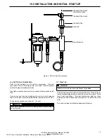
10.5 DEW POINT TRANSMITTER INSTALLATION (OPTIONAL)
On dryers equipped with EMS, the dew point transmitter is shipped in a
separate container within the electrical enclosure to protect the
transmitter during shipment. Prior to using the EMS feature, the
transmitter must be installed in the sensor block located on the side of
or behind the electrical enclosure and the transmitter cable fastened to
the sensor. Note that the transmitter should only be installed when the
dryer is ready to be commissioned.
To install the Dew Point Transmitter:
• Remove Transmitter from original packaging.
• Verify that Washer is placed below Transmitter hex.
• Thread the Transmitter into the Sensor Block as shown.
• Attach the Transmitter Cable to the Transmitter. Be sure to fully
engage the Transmitter Cable Securing Screw into the mating thread in
the Transmitter.
14
HB Series Desiccant Dryer Models 150-8000
ingersollrandproducts.com
120.26 Dryer - Operation, Installation, Maintenance Manual, and Parts


