15
HB Series Desiccant Dryer Models 150-8000
ingersollrandproducts.com
10.0 INSTALLATION AND INITIAL START-UP
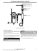
SENSING BLOCK
WASHER
TRANSMITTER
TRANSMITTER CABLE
TRANSMITTER CABLE
SECURING SCREW
Figure 4 - HB Dew Point Sensor Assy
10.6 ELECTRICAL CONNECTION
Refer to wiring diagram for all electrical connections. Electrical
connection must be hard piped with an external fused disconnect
switch with proper overload protection.
Size field connection knock-out for the conduit fitting required by the
NEC.
Service wires must be sized according to the minimum circuit ampacity
shown on the dryer serial nameplate and the requirements of the NEC.
The power connections are marked L1, L2 and L3.
A
CAUTION
Dryer must be grounded with the full sized ground wire connected to
an earth ground.
10.7 START-UP
• With dryer de-energized, slowly pressurize the dryer. When the dryer
reaches full operating pressure, check the system for air leaks. Soap
test all joints and fittings. To maintain desired dew point, any leaks
detected must be repaired, especially those on the outlet side of the
dryer.
• Turn on dryer disconnect switch to apply power to the dryer.
A
NOTICE
Initial dryer start-up must be in the Blower Purge Mode
120.26 Dryer - Operation, Installation, Maintenance Manual, and Parts

