background image

MAINTENANCE SECTION

19

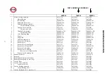
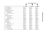
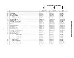
 PART NUMBER FOR ORDERING

500PS3

700PS3

900PS4

63

Check Valve Piston . . . . . . . . . . . . . . . . . . . . . . . . . . . . . . . . . . . . . . . . . . . . 

04352100

04354163

04354874

64

Piston Spring . . . . . . . . . . . . . . . . . . . . . . . . . . . . . . . . . . . . . . . . . . . . . . . . . 

04352118

04354171

04354882

65

Check Valve Ball . . . . . . . . . . . . . . . . . . . . . . . . . . . . . . . . . . . . . . . . . . . . . . 

04351904

04351904

500P–333

66

Drive Shaft Assembly . . . . . . . . . . . . . . . . . . . . . . . . . . . . . . . . . . . . . . . . . . 

04352134

04354189

04354890

67

Socket Retaining Pin . . . . . . . . . . . . . . . . . . . . . . . . . . . . . . . . . . . . . . .  5020–716

5020–716

5020–716

68

Retaining Pin Spring . . . . . . . . . . . . . . . . . . . . . . . . . . . . . . . . . . . . . . .  401–718

401–718

401–718

69

Drive Shaft Blade (2) . . . . . . . . . . . . . . . . . . . . . . . . . . . . . . . . . . . . . . . . . . . 

EQ208S–220

700PS3–220

EQ212P–220

70

Blade Spring (2) . . . . . . . . . . . . . . . . . . . . . . . . . . . . . . . . . . . . . . . . . . . . . . . 

04352142

04354205

EQ212P–219

71

Front Liner Cover Assembly . . . . . . . . . . . . . . . . . . . . . . . . . . . . . . . . . . . . . 

04352159

04352159

04354908

72

Adjustment Screw (2) . . . . . . . . . . . . . . . . . . . . . . . . . . . . . . . . . . . . . .  EQ208S–230

EQ208S–230

1900P–230

73

Oil Plug . . . . . . . . . . . . . . . . . . . . . . . . . . . . . . . . . . . . . . . . . . . . . . . . . . . . . 

EQ106S–277

EQ106S–277

EQ106S–277

74

Oil Plug Seal Support . . . . . . . . . . . . . . . . . . . . . . . . . . . . . . . . . . . . . . . . . . 

EQ106S–229

EQ106S–229

EQ106S–229

75

Oil Plug Seal . . . . . . . . . . . . . . . . . . . . . . . . . . . . . . . . . . . . . . . . . . . . . . . . . 

EQ106S–228

EQ106S–228

EQ106S–228

76

Drive Shaft O–ring . . . . . . . . . . . . . . . . . . . . . . . . . . . . . . . . . . . . . . . . . . . . 

EQ208S–271

EQ208S–271

EQ110P–271

77

Seal Back–Up Ring . . . . . . . . . . . . . . . . . . . . . . . . . . . . . . . . . . . . . . . . . . . . 

EQ106S–272

EQ106S–272

EQ110P–272

78

Front Liner Cover Piston Seal (2) . . . . . . . . . . . . . . . . . . . . . . . . . . . . . . . . . 

EQ208S–238

EQ208S–238

EQ212P–238

79

Front Mechanism Spacer . . . . . . . . . . . . . . . . . . . . . . . . . . . . . . . . . . . . . . . . 

–––

–––

04354916

80

Hammer Case Gasket . . . . . . . . . . . . . . . . . . . . . . . . . . . . . . . . . . . . . . . . . . 

04352175

04354213

04354924

81

Drive Shaft Packing

0.2 mm thick . . . . . . . . . . . . . . . . . . . . . . . . . . . . . . . . . . . 

04352183

04352183

04354932

0.3 mm thick . . . . . . . . . . . . . . . . . . . . . . . . . . . . . . . . . . . 

04352191

04352191

04354940

0.5 mm thick . . . . . . . . . . . . . . . . . . . . . . . . . . . . . . . . . . . 

04352209

04352209

04354957

Hammer Case Assembly . . . . . . . . . . . . . . . . . . . . . . . . . . . . . . . . . . . . . . . . 

04352217

04354221

04354965

82

Hammer Case . . . . . . . . . . . . . . . . . . . . . . . . . . . . . . . . . . . . . . . . . . . . .  04352225

04354239

04354973

83

Hammer Case Bearing . . . . . . . . . . . . . . . . . . . . . . . . . . . . . . . . . . . . . .  04352233

04352233

04354981

84

Adjustment Hole Plug . . . . . . . . . . . . . . . . . . . . . . . . . . . . . . . . . . . . . .  180PQ–95

180PQ–95

180PQ–95

85

Hammer Case Cap Screw (3) . . . . . . . . . . . . . . . . . . . . . . . . . . . . . . . . . . . . 

500PQ–638

500PQ–638

1410P–638

86

Cap Screw Lock Washer (3) . . . . . . . . . . . . . . . . . . . . . . . . . . . . . . . . . . . . . 

500P–58

500P–58

900P–58

Summary of Contents for 500PS3

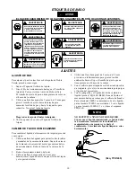
Page 1: ...e and are tightly secured See Dwg TPD905 1 for a typical piping arrangement Always use clean dry air at 90 psig 6 2 bar 620 kPa maximum air pressure Dust corrosive fumes and or excessive moisture can ruin the motor of an air tool Do not lubricate tools with flammable or volatile liquids such as kerosene diesel or jet fuel Do not remove any labels Replace any damaged label USING THE TOOL Always wea...

Page 2: ...ustment Screw 3 Using either a 2 mm or a 1 5 mm hex wrench rotate the Adjustment Screw clockwise to increase the torque output and counterclockwise to decrease the torque output Do not rotate the Oil Plug Make all final adjustments at the job 4 Replace the Adjustment Hole Plug CHANGING THE MECHANISM FLUID To change the Mechanism Fluid in the Impulse Mechanism proceed as follows 1 Using a hex wrenc...

Page 3: ...QUE ADJUSTMENT for specific adjustment procedures 15 If the torque is satisfactory but the tool fails to shut off only then is it necessary to adjust the shut off mechanism If it should become necessary proceed as follows a Remove the Adjusting Hole Plug from the Hammer Case b Using a pointed probe pick the paint out of the wrench opening in the Adjustment Screw that is 180 degrees away from the T...

Page 4: ...Handle Chuck Drive Free Speed Recommended Torque Range in Soft Draw ft lb Nm Hard Slam ft lb Nm 500PS3 pistol 3 8 sq 10 500 10 20 14 27 20 40 28 54 700PS3 pistol 3 8 sq 9 250 20 30 27 41 35 60 47 81 900PS4 pistol 1 2 sq 8 000 30 40 41 54 55 70 75 95 ...

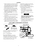
Page 5: ...um de 6 2 bar 620 kPa La poussière les fumées corrosives et ou une humidité excessive peuvent endommager le moteur d un outil pneumatique Ne jamais lubrifier les outils avec des liquides inflammables ou volatiles tels que le kérosène le gasol ou le carburant d aviation Ne retirer aucune étiquette Remplacer toute étiquette endommagée UTILISATION DE L OUTIL Porter toujours des lunettes de protection...

Page 6: ...éder comme suit 1 Retirer le bouchon du trou de réglage 2 Tourner l arbre d entraînement jusqu à ce que la vis de réglage de couple soit visible dans l ouverture Il n y a pas de peinture couleur dans la tête de la vis de réglage de couple 3 À l aide d une clé pour six pans creux de 2 mm ou de 1 5 mm tourner la vis de réglage dans le sens des aiguilles d une montre pour augmenter le couple et dans ...

Page 7: ...le de 2 3 à 2 8 Nm 12 Placer une nouvelle garniture de carter de marteau sur le corps de moteur et installer le mécanisme assemblé sur l arbre du rotor 13 Placer le couvercle de carter de marteau sur l arbre d entraînement et contre le corps et son joint Monter les trois vis à six pans creux du carter de marteau et les rondelles frein Serrer chaque vis à un couple de 5 1 à 5 6 Nm 14 Tester le coup...

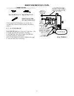
Page 8: ...r et remplir l ensemble de mécanisme d impulsion conformément aux instructions du manuel en utilisant le nécessaire de fluide de remplacement Réf No EQ106S K400 Lubrifier l entraîneur hexagonal et l arbre de sortie avant l assemblage TUYAUTERIE PRINCIPALE AU MOINS 3 FOIS LA DIMEN SION DE L ADMISSION D AIR DE L OUTIL VERS LE RÉSEAU D AIR COMPRIMÉ VERS L OUTIL PNEU MATIQUE LUBRIFICATEUR RÉGULATEUR F...

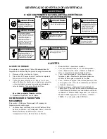
Page 9: ...áxima presión de 90 psig 6 2 bar 620 kPa El polvo los gases corrosivos y o el exceso de humedad podrían estropear el motor de una herramienta neumática No lubrique las herramientas con líquidos inflamables o volátiles tales como queroseno gasoil o combustible para motores a reacción No saque ninguna etiqueta Sustituya toda etiqueta dañada USO DE LA HERRAMIENTA Use siempre protección ocular cuando ...

Page 10: ... tiene pintura de color en el hueco de la cabeza 3 Utilice una llave hexagonal de 2 mm o de 1 5 mm para girar el tornillo de ajuste hacia la derecha para aumentar la salida de par y hacia la izquierda para reducirlo No gire el tapón del aceite NOTA Haga todos los ajustes finales trabajando 4 Vuelva a poner en su sitio el Tapón de Orificio de Ajuste CAMBIO DE FLUIDO DE MECANISMO Para cambiar el líq...

Page 11: ...orio pero la herramienta no se detiene habrá que ajustar el mecanismo de parada En tal caso proceda de la forma siguiente a Quite el tapón del orificio de ajuste de la carcasa de la maza b Saque escarbando con un útil con punta la pintura del hueco de la cabeza del tornillo de ajuste que queda a 180 grados del tornillo de ajuste del par c Gire el tornillo hacia la izquierda no más de diez grados N...

Page 12: ...905 1 para um arranjo típico de tubagem Use sempre ar seco e limpo com pressão máxima de 90 psig Pó fumos corrosivos e ou humidade excessiva podem arruinar o motor de uma ferramenta pneumática Não lubrifique as ferramentas com líquidos inflamáveis ou voláteis tais como querosene diesel ou combustível de jactos Não remova nenhum rótulo Reponha qualquer rótulo danificado USANDO A FERRAMENTA Use semp...

Page 13: ...étricas de Impulsão de Lâminas Duplas proceda da seguinte maneira 1 Remova o Bujão do Furo de Ajuste 2 Gire o Eixo de Comando até o Parafuso de Ajuste de Torque estar visível na abertura 3 Com uma chave sextavada de 2 mm ou de 1 5 mm rode o Parafuso de Ajuste para a direita para aumentar o valor de binário e para a esquerda para diminuir o valor de binário Não gire o Bujão de Óleo AVISO Faça todos...

Page 14: ...aixa do Martelo sobre o Veio de Accionamento contra a Carcaça e a Junta Instale os três Parafusos Allen da Caixa do Martelo e as Contraporcas Aperte cada parafuso com um valor de binário entre 5 1 e 5 6 Nm 14 Teste a ferramenta quanto ao binário nos ajustes máximo mínimo e médio de binário Se a ferramenta não funcionar satisfatoriamente repita o processo de enchimento e preste atenção especial à r...

Page 15: ... 000 ciclos ou como a experiência indicar drene e encha o Conjunto do Comando da Unidade de Impulso como instruído neste manual usando o Kit de Reposição de Fluido Número de Pedido EQ106S K400 Lubrifique o comando hexagonal e o eixo de saída antes de montar LINHAS PRINCIPAIS 3 VEZES O TAMANHO DA ENTRADA DA FERRAMENTA PNEUMÁTICA PARA SISTEMA DE AR PARA FERRAMENTA PNEUMÁTICA LUBRIFICADOR REGULADOR F...

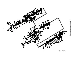
Page 16: ...MAINTENANCE SECTION 16 Dwg TPA1481 ...

Page 17: ... 120 180PQ 120 14 Reverse Valve Bushing 04351771 04351771 04351771 15 Reverse Valve 04351789 04351789 04351789 16 Reverse Valve Detent Spring 04351797 04351797 04351797 17 Reverse Valve Detent Ball EQ104S 929 EQ104S 929 EQ104S 929 18 Reverse Valve Retainer 500PQ 303 500PQ 303 500PQ 303 19 Reverse Lever Assembly 04351805 04351805 04351805 20 Reverse Lever Alignment Pin 04351813 04351813 04351813 21...

Page 18: ...Front End Plate 04351995 04354130 04354825 45 Front Rotor Bearing EQ106S 22 EQ106S 22 R38P 606 46 End Plate Alignment Dowel EQ106P 99 EQ106P 99 EQ106P 99 47 Liner Housing EQ208S 240 EQ210S 240 EQ112P 240 48 Liner Housing Seal 2 EQ208S 236 EQ208S 236 EQ212P 236 49 Housing Cap EQ106S 207 EQ106S 207 EQ110P 207 50 Rear Liner Cover 04352001 04352001 04354833 51 Rear Liner Cover Seal EQ208S 237 EQ208S 2...

Page 19: ... 277 74 Oil Plug Seal Support EQ106S 229 EQ106S 229 EQ106S 229 75 Oil Plug Seal EQ106S 228 EQ106S 228 EQ106S 228 76 Drive Shaft O ring EQ208S 271 EQ208S 271 EQ110P 271 77 Seal Back Up Ring EQ106S 272 EQ106S 272 EQ110P 272 78 Front Liner Cover Piston Seal 2 EQ208S 238 EQ208S 238 EQ212P 238 79 Front Mechanism Spacer 04354916 80 Hammer Case Gasket 04352175 04354213 04354924 81 Drive Shaft Packing 0 2...

Page 20: ...WARNING 2 99 Hex Wrench 1 5 mm 55P3 900 55P3 900 2 0 mm 04355012 5 0 mm 04352258 04352258 04352258 Repair Fixture 04355178 04355178 04355178 Fluid Replacement Kit EQ106S K400 EQ106S K400 EQ106S K400 Replacement Fluid 4 oz EQ106S 400 1 EQ106S 400 1 EQ106S 400 1 Replacement Fluid 1 gal EQ106S BF400 1 EQ106S BF400 1 EQ106S BF400 1 Tool Kit includess all the specialized tooling required to repair thes...

Page 21: ...t large end downward on a workbench or the table of an arbor press Insert the output end of the Drive Shaft into the central opening and either tap the Housing downward off the components or use the Pressing Sleeve in the Kit to press the Housing downward off the components Refer to Dwg TPD1268 PRESSING SLEEVE TAP EDGE LIGHTLY WITH BRASS HAMMER OR USE PRESSING SLEEVE FROM TOOL KIT DISASSEMBLY ARBO...

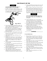
Page 22: ...et Bushing 2 and Exhaust Deflector Assembly 22 19 Insert a threaded rod through the Cylinder and Front End Plate and install a nut and washer on the end plate end of the rod Position the Rear End Plate on the threaded rod against the Cylinder and clamp the End Plates and Cylinder snug with another nut and washer Do not tighten the assembly excessively In the following step take all precautions nec...

Page 23: ...or until the End Plate contacts the shim Remove the shim Refer to Dwg TPD1275 PRESSING PLUG FRONT ROTOR BEARING ROTOR PLATE WITH ROTOR SHAFT CLEARANCE FRONT END PLATE 0 001 0 025 mm SHIM SPACE Dwg TPD1275 10 Coat each Vane 43 with a thin film of oil and insert a Vane into each of the rotor vane slots with the straight edge of the Vane outward 11 Install the Cylinder 41 over the Vanes and Rotor mak...

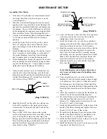
Page 24: ...in the end face of the opposite wall Insert the Check Valve Piston 63 large end trailing and the Check Valve Ball 65 into the same opening 4 Thread the Threaded Tee Wrench furnished with the Tool Kit into the end of the Check Valve Assembly and using the Wrench to hold the Assembly insert the Assembly into the opening against the Ball 5 Unscrew the Wrench and screw it into the Piston Stop Assembly...

Page 25: ...Do not Damage the Seals during installation 17 Grasp the flats of the Liner Housing in vise jaws and using the Spanner Plug furnished with the Tool Kit and a torque wrench install the Housing Cap castellated end leading This is a left hand thread rotate the wrench counterclockwise to tighten the Cap Tighten the Cap on models 500PS3 and 700PS3 between 9 4 and 10 7 ft lb 12 7 and 14 5 Nm torque and ...

Reviews: