Form 32048-EU
Edition 2
December 1994
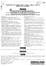
INSTRUCTIONS FOR MODELS BMDLL-4, BMDLL-6, BMDLL-8, BMDLL-10
MEDIUM DUTY BALANCERS
IMPORTANT SAFETY INFORMATION ENCLOSED.
READ THIS MANUAL BEFORE OPERATING BALANCER.
IT IS THE RESPONSIBILITY OF THE EMPLOYER TO PLACE THE INFORMATION
IN THIS MANUAL INTO THE HANDS OF THE OPERATOR.
FAILURE TO OBSERVE THE FOLLOWING WARNINGS COULD RESULT IN INJURY.
FORSEEN USE
Model BMDLL Medium Duty Balancers are designed to
counter-balance the weight of Power Tools.
Ingersoll-Rand is not responsible for customers using these
balancers for other applications on which Ingersoll-Rand was
not consulted.
PLACING BALANCER IN SERVICE
Always operate, inspect and maintain this balancer in
accordance with all regulations (Local, state, federal and
country), that may apply to hand held, hand operated power
tools and balancers.
Calculate the total load to be supported by the balancer:
equipment, accessories and those sections of hose or cable to
be lifted by the balancer. The whole load to be balanced must
be within the specified capacity range of the balancer. (See
balancer capacity shown in the specifications).
To achieve the best performance, hang the balancer in A for
capacities up to 4 kg (Fig1a) and in A for higher capacities
(Fig 1 b), at a height which allows the use of the central sectlon
of the cable stroke 11.
Connect the suspension in the free hole with a flexible cable to
a suitable support leaving a maximum extra stroke of 100mm
(Fig.1a -1b). The balancer must be free to line up with the load
. if screwed fasteners are used to connect the balancer at point
A, or S, either self locking systems and/or split pins should be
used
Hang the load on the hook 15
. Do not lubricate balancers with flammable or volatile liquids
such as kerosene, diesel or jet fuel.
Do not remove any labels. Replace any damaged label.
USING THE BALANCER
When the balancer with its load is installed, check that working
conditions are correct (smooth movement with minimum
effort).
For a correct and safe use periodically check the status of the
upper attachments A and S (if screws are used, the status of
self locking systems and/or split pins should be checked).
Periodically check that parts under strain (hook, cable,
balancer suspension parts and connections to the tool) are
safe and not weakened by wear.
ADJUSTMENTS
To increase capacity rotate the axis F counter-clockwise
using a wrench D (Fig. 2).
To decrease capacity, press spring 8 in a clockwise direction
whilst rotating axis F counter-clockwise using a wrench D (Fig.
3).
During working the cable must not unwind its total length. It
must stop at least 50mm before the lower limit of the stroke. If
necessary adjust the clamp 13 to limit the upwards stroke (Fig.
4).
Since a correct spring tension keeps the drum rotating freely,
the balancer must not be used for lesser loads than its
minimum capacity.
If the drum blocks during initial adjustment, it could be due to
an insufficient load. increase capacity using the wrench D as in
(Fig 2) Check that with the cable 11 completely wound, the
working is regular.
If the drum blocks with the load at the top of the stroke,
proceed as in the previous section, increasing the capacity, or
by limiting the upwards stroke by adjusting clamp 13 If this
does not solve the problem, replace the balancer with one of a
lower capacity
REWIND BLOCKING FEATURE
An exclusive feature of this series of balancers is a
mechanism which blocks the rewinding of the cable; this
makes it possible to work without cable tension, for example,
inside a car (Fig 7).
With sufficient cable out of the balancer, the rewind block is
activated by a slow retraction of a short length of the cable,
causing ratchet E to click into the housing C through the force
of gravity (Fig.8).
The rewind block
IS
cancelled when the cable is pulled
downwards.
To prevent accidental blocking, the upstroke should take place
at normal speed.
The rewind blocking mechanism can be neutralized by
tightening home the screw 21, while the load is pulled up and
down manually (Fig 9).
The main balancing spring, together with its housing drum and the centrifugal safety disc are only supplied as one complete item (5).
It
IS
dangerous for unqualified personnel to dismantle this balancer
The use of other than Ingersoll-Rand replacement parts may result in safety hazards, decreased performance and increased
maintenance, and may invalidate all warranties. Repairs should be made only by authorised trained personnel. Consult your nearest
Ingersoll-Rand Authorised Service Centre.
SAVE THESE INSTRUCTIONS, DO NOT DESTROY.
When the life of the balancer has expired, it should be returned to the nearest Authorised Ingersoll-Rand Service Center for
dismantling and recycling.
Refer all Communications to the nearest
Ingersoll-Rand Office or Distributor.
0 Ingersoll-Rand Company 1994
Printed in Italy
PROFESSIONALTOOLS
All manuals and user guides at all-guides.com
Summary of Contents for BMDLL-10
Page 2: ...All manuals and user guides at all guides com...
Page 3: ...All manuals and user guides at all guides com...
Page 4: ...All manuals and user guides at all guides com...
Page 5: ...All manuals and user guides at all guides com...
Page 6: ...All manuals and user guides at all guides com...
Page 7: ...All manuals and user guides at all guides com...
Page 8: ...All manuals and user guides at all guides com...
Page 9: ...All manuals and user guides at all guides com...
Page 10: ...All manuals and user guides at all guides com...
Page 11: ...All manuals and user guides at all guides com...
Page 12: ...All manuals and user guides at all guides com...
Page 13: ...All manuals and user guides at all guides com...
Page 14: ...All manuals and user guides at all guides com...
Page 15: ...All manuals and user guides at all guides com...
Page 16: ...All manuals and user guides at all guides com...

