background image

27

( )

Book 22464945 (1/07)

SECTION 5 -- MAINTENANCE

GENERAL

In addition to periodic inspections, many of the
components in these units require periodic servicing to
provide maximum output and performance. Servicing
may consist of pre--operation and post--operation
procedures to be performed by the operating or
maintenance personnel. The primary function of
preventive maintenance is to prevent failure, and
consequently, the need for repair.

Preventive

maintenance is the easiest and the least expensive
type of maintenance. Maintaining your unit and
keeping it clean at all times will facilitate servicing.
Refer to the engine Operator’s Manual furnished in
this manual for the specific requirements on
preventive maintenance for the engine.

SCHEDULED MAINTENANCE

The maintenance schedule is based on normal
operation of the unit. This page can be reproduced
and used as a checklist by the service personnel. In
the event unusual environmental operating conditions
exist, the schedule should be adjusted accordingly.

COMPRESSOR OIL LEVEL

The oil level is most consistent when the unit is

RUNNING AT FULL LOAD and should be checked at

this time. The optimum operating level is midway of the

sight tube on the side of the receiver tank. See the

decal beside the sight tube. If the oil level is not in the

“OK” range, make appropriate corrections (Add or

Drain). A totally filled sight tube in which the level is not

visible indicates an over--full condition and requires

that oil be drained.

If necessary, Refer to Lubrication Section for recom-

mended lubricant.

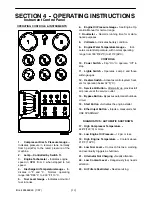
AIR CLEANER

This unit is equipped with an AIR FILTERS
RESTRICTED lamp on the instrument panel, covering
both the engine and the compressor.

This should be checked daily during operation. If the
lamp glows (red) with the unit operating at full speed,
servicing of the cleaner element is necessary.

Also weekly squeeze the rubber valve (precleaner dirt
dump) on each air cleaner housing to ensure that they
are not clogged.

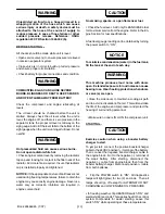
NOTICE:

Holes or cracks downstream of the air

cleaner housing will cause the restriction indicators to
be ineffective.

The air filters restricted sensor will automatically reset
after the main power switch is flipped to “OFF.”

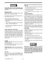
1.

Loosen outer wing nut and remove with outer
element. Remove loose inner wing nut and in-
ner (safety) element.

2.

Inspect air cleaner housing for any condition
that might cause a leak and correct as neces-
sary.

3.

Wipe inside of air cleaner housing with a clean,
damp cloth to remove any dirt accumulation,
especially in the area where the element seals
against the housing.

4.

Inspect the primary element by placing a bright
light inside and rotating slowly. If any holes or
tears are found in the paper, discard this ele-
ment. If no ruptures are found, the element can
be cleaned by one of the following procedures.

Do not clean the safety element. Replace it with

a new element.

5.

Check new air filter elements for any shipping
damage.

6.

Install cleaned or new elements in the reverse
order to the above. Tighten wing nuts firmly.

7.

Inspect to ensure that the end cap seals tightly
360 degrees around the air cleaner body.

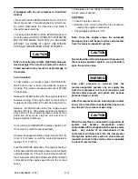
In the event that the filter element must be reused
immediately, compressed air cleaning (as follows) is
recommended since the element must be thoroughly
dry. Direct compressed air through the element in the
direction opposite to the normal air flow through the
element.

Move the nozzle up and down while rotating the ele-
ment. Be sure to keep the nozzle at least one inch
(25.4 mm) from the pleated paper.

NOTICE

To prevent damage to the element, never exceed a
maximum air pressure of 100 psi (700 kPa).

Summary of Contents for CSA XHP900WCAT

Page 1: ...erate and maintain this machine XHP900WCAT Code B Revised 10 12 Doosan purchased Bobcat Company from Ingersoll Rand Company in 2007 Any reference to Ingersoll Rand Company or use of trademarks service marks logos or other proprietary identifying marks belonging to Ingersoll Rand Company in this manual is historical or nominative in nature and is not meant to suggest a current affiliation between I...

Page 2: ...nd services that consistently meet the requirements of our customers and each other CALIFORNIA Proposition 65 Warning Diesel engine exhaust and some of its constituents are known to the State of California to cause cancer birth defects and other reproductive harm ...

Page 3: ...t countries requires that the machine display the EC Mark and conform to various directives In such cases the design specification of this machine has been certified as complying with EC directives Any modification to any part is absolutely prohibited and would result in the CE certification and marking being rendered invalid A declaration of that conformity follows ...

Page 4: ...______ Represented In EC By Ingersoll Rand Company Limited Swan Lane Hindley Green Wigan WN2 4EZ United Kingdom Issued at Mocksville on 1 1 95 Issued at Hindley Green on 1 1 95 ________________________________ EN1012 1 EN29001 EN292 EN60204 1 PN8NTC2 EN 50081 EN50082 HP1300WCU XP1400WCU P1600WCU XP900WCU XHP900WCAT XHP650WCAT XHP750WCAT XHP825WCAT VHP825WCU HP935WCU XP1050WCU HP825WCU VHP750WCAT V...

Page 5: ...changes or add such improvements to products sold previously Theintendedusesofthismachine areoutlined belowand examplesofunapprovedusage arealso given However Ingersoll Rand cannot anticipate every application or work situation that may arise If in doubt consult supervision This machine has been designed and supplied for above ground operation to be used for compression of normal ambient air conta...

Page 6: ...nstructions should be carefully read to obtain a thorough knowledge of the duties to be performed Please take pride in the compressor keep it clean and in good mechanical condition To enable proper maintenance records Ingersoll Rand provides a Noise Emission ControlMaintenance LogBook PCD Form 685 with each compressor shipped from the factory This Log Book contains a recommended schedule and space...

Page 7: ...7 Book 22464945 1 07 TABLE OF CONTENTS SECTION 1 SAFETY SECTION 2 NOISE EMISSION SECTION 3 GENERAL DATA SECTION 4 OPERATION SECTION 5 MAINTENANCE SECTION 6 LUBRICATION SECTION 7 TROUBLESHOOTING ...

Page 8: ...must be fitted and controlled by work procedures so that one machine cannot accidentally be pressurized or over pressurized by another Compressed air must not be used for a feed to any form of breathing apparatus or mask The discharged air contains a very small percentage of compressor lubricating oil and care should be taken to ensure that downstream equipment is compatible If the discharged air ...

Page 9: ...ous burns Do not open radiator while hot Rotating fan blade can cause serious injury Do not operate without guard in place Use care to avoid contacting hot surfaces engine exhaust manifold and piping air receiver and air discharge piping etc Ether is an extremely volatile highly flammable gas USE SPARINGLY Do NOT use ETHER if unit has GLOW Plug starting aid Engine damage will result Never allow th...

Page 10: ...s WARNING Flammable liquid Air gas flow or Air discharge Look forthese signs onmachines shippedtointernationalmarkets outside NorthAmerica whichpoint out potential hazards to the safety of you and others Read and understand thoroughly Heed warnings and follow instructions If you do not understand inform you supervisor handbrake and wheel chocks Diesel Fuel No open flame Do not breathe the compress...

Page 11: ...anual Rough Service Designation Wet Location Operation WARNING Consult the operation and maintenance manual before performing any maintenance WARNING Before connecting the tow bar or when preparing to tow consult the operation and maintenance manual Replace any cracked protective shield On power Off power Emergency stop Do not use fork lift truck from this side Do not stack Do not operate with the...

Page 12: ... and Maintenance manual before operation or maintenance of this machine is undertaken XX km h Pressurized component or system Do not exceed the speed limit Pressurized vessel Do not remove the Operating and Maintenance manual and manual holder from this machine Use fork lift truck from this side only 0_C WARNING For operating temperature below 0_C consult the operation and maintenance manual ...

Page 13: ...arkets in North America which point out potential hazards to the safety of you and others Read and understand thoroughly Heed warnings and follow instructions If you do not understand inform you supervisor Discharged air can contain carbon monoxide or other contaminants DANGER Do not breathe this air Will cause serious injury or death Can cause serious injury or death Trapped air pressure Close se...

Page 14: ...th 105 km hr Rotating fan blade Can cause serious Do not operate without guard in place WARNING injury Falling off machine Can cause serious injury Access lifting bail from inside machine or death WARNING Door under pressure Can cause serious injury Use both hands to open door when machine is running WARNING attach safety device OSHA Valve at source of When using air tools Can cause serious WARNIN...

Page 15: ... safety Assure that decals are present on the machines Replace decals that are not readable FREE SAFETY DECALS CAUTION This engine is equipped with an electric heater starting aid DO NOT USE ETHER ENGINE DAMAGE WILL OCCUR High pressure air Can cause serious Relieve pressure before removing filler plugs caps fittings or covers injury or death WARNING COOLANT FILL INSTRUCTIONS Adding Replacing NOTIC...

Page 16: ... the air intake system or parts thereof c enclosure or parts thereof 2 Removal of any of the following a fan shroud b vibration mounts c sound absorption material 3 Operation of the compressor with any of the enclosure doors open Compressor Noise Emission Control Information A The removal or rendering inoperative other than for the purpose of maintenance repair or replacement of any noise control ...

Page 17: ...he manufacturer warrants to the ultimate purchaser and each subsequent purchaser that this air compressor was designed built and equipped to conform at the time of sale to the first retail purchaser with all applicable U S EPA Noise Control Regulations This warranty is not limited to any particular part component or system of the air compressor Defects in the de sign assembly or in any part compon...

Page 18: ...E Enclosure Panels Enclosure panels should also be inspected at 100 hour operational intervals All panels that are warped punctured torn or otherwise deformed such that their noise containment function is reduced should be re paired or replaced before the next operation interval Doors access panels and hatch closures especially should be checked and adjusted at this time to insure continuous seati...

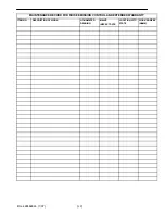
Page 19: ...19 Book 22464945 1 07 MAINTENANCE RECORD FOR NOISE EMISSION CONTROL AND EXTENDED WARRANTY ITEM NO DESCRIPTION OF WORK HOURMETER READING MAINT INSPECT DATE LOCATION CITY STATE WORK DONE BY NAME ...

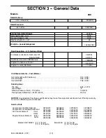
Page 20: ...adiator Unit Measurements Feet Meters Tire Size 8 25 x 15TR Load Range F Inflation Pressure Cold PSI kPa 105 720 Towing Speed Maximum MPH km hr 20 32 Running Gear 36758613 36762250 35123520 35123512 35355353 35355395 36758613 36762250 35123520 35123512 35355353 35355395 36758613 36762250 35123520 35123512 35355353 35355395 36758613 36762250 36864379 36864361 36864379 36864361 Compressor Oil Filter...

Page 21: ...e Indi cates coolant temperature with normal operating range from 180 F 82 C to 210 F 99 C CONTROLS 10 Power Switch Flip On to operate Off to stop 11 Lights Switch Operates Lamp 2 and those within gauges 12 Heaters Switch Activates control system heat ers for operation below 32 F C 13 Service Air Button After warm up provides full air pressure at the service outlet 14 Bypass Button Bypasses automa...

Page 22: ... is to be operated out of level it is important 1 Tokeep theengine crankcaseoillevelnear thehigh level mark with the unit level 2 To have the compressor oil level gauge show no more than mid scale Do not overfill the engine crankcase or the compressor Compressor Mounting Portable compressors which are modified to remove the running gear and mount the machine direct to trailers truck beds or frames...

Page 23: ...rain the engine may cause costly engine damage Never use water only as corrosion inhibitors are required in engine coolant fluid CAUTION No smoking sparks or open flame near fuel Check the fuel level Add only CLEAN DIESEL fuel for maximum service from the engine Refer to the En gine Section for fuel specifications A fuel level gauge reading can be obtained by turning the power switch to ON NOTICE ...

Page 24: ...ten 10 minutes or until the coolant temperature reaches 140 F 60 C Push the SERVICE AIR button The engine should go to full speed and the discharge pressure rise to slightly over rated pressure If there is no air being consumed the compressor will unload intake should be throttled or closed and the engine speed drop to the no load speed Compressor is now ready to furnish air when the service valve...

Page 25: ...utdown situation thefunction ofthe panellamps is to indicate what specific failure caused the unit to shut down These lamps will remain illuminated until the Power Switch is turned OFF Note None of the panel lamps should be glowing when machine is operating If they are shut unit down and investigate The upper four 4 lamps are electronically latched to only respond to the first or primary signal fo...

Page 26: ...d bearing 7 Take slack out of spring G by moving nuts E and F Tighten nuts XHP 900 Units ONLY Adjust spring so it is full stretched and nut F is at far end of rod closest to spring G Tighten nuts 8 Start unit and allow to warm up for 3 to 5 min utes 9 Push Service Air button on control panel 10 With service air valve closed adjust pressure regulator PR to rated pressure plus 10 psi 70 kPa as follo...

Page 27: ...checked daily during operation If the lamp glows red with the unit operating at full speed servicing of the cleaner element is necessary Also weekly squeeze the rubber valve precleaner dirt dump on each air cleaner housing to ensure that they are not clogged NOTICE Holes or cracks downstream of the air cleaner housing will cause the restriction indicators to be ineffective The air filters restrict...

Page 28: ...uld be repaired or re placed Monthly check the wheel lug nuts for tight ness AUTOMATIC SHUTDOWN SYSTEM The discharge air temperature switches will require approximately 248 F 120 C to actuate The engine coolant temperature switch will require approximately 215 F 102 C to actuate Replace any defective switch before continuing to operate the unit A low oil pressure switch may be tested by removing i...

Page 29: ...exible hoses used for air oil and fuel be inspected To ensure freedom from air leaks all rubber hose joints and the screw type hose clamps must be abso lutely tight Regular inspection of these connections for wear or deterioration is a definite must if regulator servicing of the air cleaners is not to prove futile Pre mature wear of both the engine and compressor is AS SURED whenever dust laden ai...

Page 30: ...b Keep lifting and pushing the bearing down into the edge of the grease pile until grease oozes out both from the top and from between the rollers Then rotate the bearing to repeat this operation on the next segment Keep doing this until you have the entire bearing completely filled with grease NOTICE Excessive grease in the hub or grease cap serves no purpose due to the fact that there is no way ...

Page 31: ...s dependent upon the operating environment soot dust etc and should be replaced every twelve months or 2000 hours To replace the element proceed as follows Ensure the tank pressure is zero Disconnect the hose from the scavenge tube Remove scavenge tube from tank cover Disconnect service line from cover Remove cover element and inner shell Remove any gasket material left on cover or tank Install ne...

Page 32: ...e Once a year or every 2000 hours of operation which ever comes first remove this line and any orifice thor oughly clean then reassemble NOTICE Excessive oil carry over may be caused by an oil logged separator element Do not replace element without first performing the following mainte nance procedure 1 Check oil level Maintain as indicated earlier in this section 2 Thoroughly clean scavenge line ...

Page 33: ... 5 Wipe the area clean using Duponts 3900S 6 Blow and tack the area to be painted 7 Apply a smooth coat of Duponts 1854S Tuffcoat Primer to all bare metal areas and allow to dry 8 Apply 2 medium wet coats of Duponts 222S Adhesion Promoter over the entire area to be painted with a 5 minute flash in between coats 9 To apply the texture coat use Duponts 1854S Tuffcoat Primer The proper technique to d...

Page 34: ...ld be cleaned to prevent dirt and other contami nants from entering the hydraulic system Whenever a brake line hose tube or fitting is removed replaced the hydraulic brake system must be bled of air to ensure proper brake operation Bleed the brakes at each wheel cylinder in the following order RH rear LH rear RH front LH front front is the hitch end instrumentpanelis on LH side while maintaining b...

Page 35: ...nd the brake shoes Adjust the brake shoes out until the pressure of the linings against the drum makes the wheel very difficult to turn 4 Then rotate the starwheel in the opposite direction until the wheel turns freely with a slight lining drag 5 Replace the adjusting hole cover and lower the wheel to the ground 6 Repeat above procedures on all brakes CAUTION Any unauthorized modification or failu...

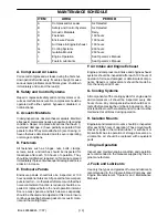
Page 36: ...eel Lug Nuts C Hoses oil air intake etc C Automatic Shutdown System Test C Air Cleaner System Visual C Compressor Oil Cooler Exterior C CLEAN Engine Radiator Exterior C CLEAN Fasteners Guards C Air Cleaner Elements WI Fuel Water Separator Element R Compressor Oil Filter Element R Compressor Oil R Wheels bearings seals etc C C Engine Coolant Test C R Shutdown Switch Settings Test C Scavenge Orifice...

Page 37: ...s or lacquers which may be insoluble Such deposits can cause se rious troubles including clogging of the filters Where possible do NOT mix oils of different types and avoid mixing differentbrands Atype or brand change is best made at the time of a complete oil drain and refill If the unit has been operated for the time hours men tioned above it should be completely drained of oil If the unit has b...

Page 38: ...C to 52_C 10_F to 125_F IR Pro Tect IR XHP 605 10_F to 125_F 23_C to 52_C 65_F to 125_F IR XHP1001 Preferred Ingersoll Rand Fluids Use of these fluids with original I R filters can extend airend warranty Refer to operator s manual warranty section for details or contact your I R representative XHP405 18_C to 52_C XHP605 Alternate IR XHP405 Preferred Preferred Alternate Preferred Consult Factory Co...

Page 39: ...of Cooling Air Loose Wire Connection Malfunctioning circuit board SECTION 7 TROUBLE SHOOTING Bold Headings depict the COMPLAINT Subheadings suggest the CAUSE Note Subheadings suggest sequence to follow troubleshooting Add CLEAN diesel Fuel See Complaint 10 Check coolant level If necessary Add See Complaint 3 and Complaint 4 Replace fan belt Wiggle wires at switches connector blocks Make repairs Re...

Page 40: ...enoid Malfunctioning Relay Defective Safety Bypass Switch Add oil Relocate or reposition See Engine Oil Spec Change oil Replace element s See Trouble Shooting in Engine Manual Repair or replace Replace circuit Replace circuit board Replace circuit board Replace circuit board Replace circuit board Tighten or replace belt set Repair or replace connection Check electrolyte level Add if necessary Chec...

Page 41: ...efective Minimum Pressure Valve Defective Separator Element Wrong Air Filter Element Above spec limit Relocate or reposition unit Add oil Look for any leaks Check spec in this manual Clean exterior surfaces Move unit to cleaner environment Replace elements Change oil Tighten or replace belt set Reduce pressure to spec Close side doors Replace belly pan Replace thermostat in bypass valve Check fan ...

Page 42: ...Unloader Butterfly Valve Defective Safety Valve Defective Separator Element Ice in Regulation Lines Orifice Move unit to cleaner environment Install new element Read procedure in this manual Install proper element Inspect coupling If necessary replace coupling Read procedure in this manual Relocate or reposition unit Remove scavenge orifice Clean and Replace Remove scavenge tube Clean and Replace ...

Reviews: