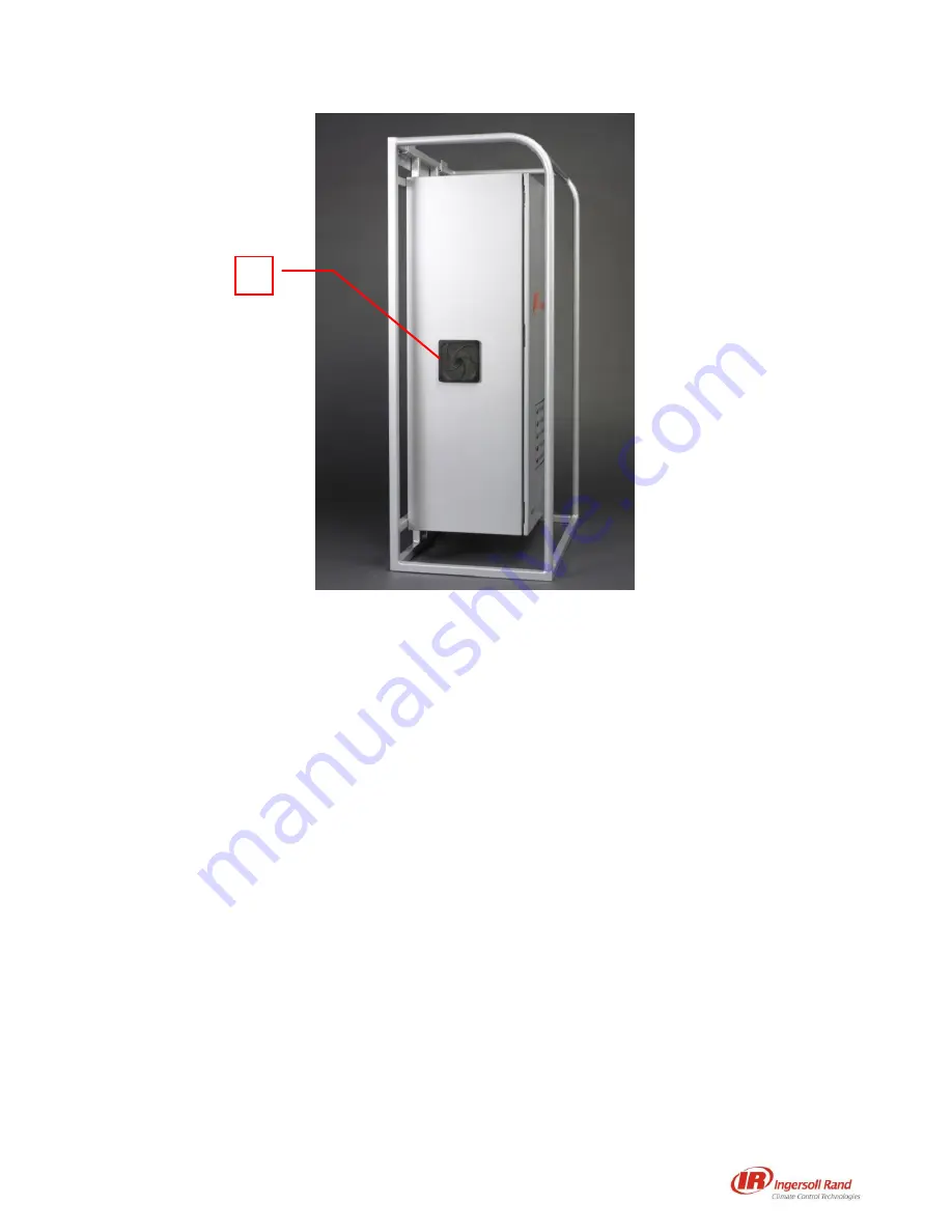
12
Figure 8. Left Side View of EMS-3300 ROS Purifier
9. Cable Entry Gland
The cable entry glands provide sealable entry points to connect to the electrical supply, and to connect the
12AWG or 14AWG wires to the control box.
10. Disconnect Switch
The disconnect switch turns the EMS-3300 ROS Purifier ON and OFF. The disconnect switch must be set
to OFF and the cabinet locks must be unlocked to open the purifier.
11. Enclosure Filter
The enclosure filter provides ventilation filtration for the EMS-3300 ROS Purifier.
12. Exhaust Outlet
The exhaust outlet is the point at which the ROS is vented into the environment.
13. Turbine Filter
The turbine filter protects the turbine and purification chambers from physical pollutants.
14. Cabinet Lock
The cabinet locks keep the EMS-3300 ROS Purifier locked and protected against unauthorized intrusion.
They must be opened and the disconnect switch must be set to OFF to open the purifier.
Figure 8 shows the factory-set configuration for the purification chambers corresponding to Medium and
High purifier output. Purification chambers 1 and 2 operate for Medium, and purification chambers 1, 2,
3 and 4 operate for High (in the original factory settings). Modifications to this configuration may be
made by the Ingersoll Rand EMS Certified Technician when the system is activated. Make note of the
new configuration in this manual.
4
Summary of Contents for EMS-3000 Series
Page 2: ......
Page 3: ...i ...
Page 5: ...iii ...
Page 7: ...v ...
Page 8: ......
Page 14: ...6 ...
Page 21: ...13 Figure 9 Factory Default Setting Within EMS 3300 ROS Purifier ...
Page 36: ...28 ...


