Only allow
Ingersoll Rand
trained technicians to perform maintenance on this product. For additional information contact
Ingersoll Rand
factory or nearest
Distributor.
For additional supporting documentation refer to Table 1 ‘Product Information Manuals’ on page 2.
Manuals can be downloaded from http://www.ingersollrandproducts.com.
The use of other than genuine Ingersoll Rand replacement parts may result in safety hazards, decreased performance and increased maintenance and will invalidate all
warranties.
Original instructions are in English. Other languages are a translation of the original instructions.
Refer all communications to the nearest Ingersoll Rand Office or Distributor.
Table 1: Product Information Manuals
Publication
Part/Document Number Publication
Part/Document
Number
Product Safety Information Manual (Non-Man Rider)
MHD56250
Product Maintenance Information Manual (Non-Man Rider)
MHD56301
Product Safety Information Manual (Man Rider)
MHD56251
Product Maintenance Information Manual (Man Rider)
MHD56304
Product Parts Information Manual
MHD56302
INSPECTION
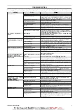
Frequent inspections should be performed on equipment in regular service. Refer
to Product Information Manual. Some options may not apply to your product, refer
to data (name) plate for correct model and any applicable manuals.
n
Periodic Inspection
Refer to Table 2 ‘Inspection Classifications’ on page 2 for suggested winch
inspection classifications for Periodic Inspection intervals. Select conditions most
appropriate to application.
Table 2: Inspection Classifications
Conditions
Normal
Heavy
Severe
Typical Use (operating time)
Infrequent
Regular
Continual/Constant
Load Range
60% of Capacity 75% of Times Used
80% of Capacity 75% of Times Used
100% of Capacity 75% of Times Used
Installation
Protected/Enclosed/Dry
Not Sheltered/Exterior
Full Exposure
Atmosphere
Clean/Non-Corrosive
Dirty/Non-Corrosive/Freshwater Marine
Dirty/Corrosive/Saltwater Marine
Climate
Dry/Stable Temperature
Wet/Moderate Temperature Fluctuations
Wet/Severe Temperature Fluctuations
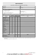
Maintain written records of periodic inspections to provide an accumulative basis
for continuing evaluation. Inspect all items listed in “Frequent Inspection.” Also
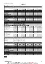
inspect the following at the suggested intervals recommended in Table 3
‘Maintenance Interval Chart’ on page 3:
1.
Siderails and Uprights. Check for deformed, cracked or corroded main
components. Replace damaged parts.
2.
Fasteners. Check retainer rings, capscrews, nuts and other fasteners on winch,
including mounting bolts. Replace if missing or damaged and tighten if loose.
3.
Drum and Sheaves. Check for cracks, wear or damage. Replace if necessary.
4.
Wire Rope. In addition to “Frequent Inspection” requirements, also inspect for
the following:
a. Build-up of dirt and corrosion. Clean with steam or a stiff wire brush to
remove dirt and corrosion if necessary.
b. Loose or damaged end connection. Replace if loose or damaged.
c. Check wire rope anchor is secure in drum.
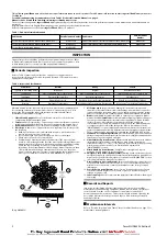
d. Verify wire rope diameter. Measure the diameter of the wire rope from
crown-to-crown throughout the life of the wire rope. Recording of the actual
diameter should only be done with the wire rope under equivalent loading
and in the same operating section as accomplished during previous
inspections. If the actual diameter of the wire rope has decreased more than
1/64 inch (0.4 mm) a thorough examination of the wire rope should be
conducted by an experienced inspector to determine the suitability of the
wire rope to remain in service. Refer to Dwg. MHP0056 on page 2.
A
B
C
D
(Dwg. MHP0056)
5.
All Components. Inspect for wear, damage, distortion, deformation and
cleanliness. If external evidence indicates damage, disassemble as required to
conduct a detailed inspection. Inspect gears, shafts, bearings, sheaves, springs
and covers. Replace worn or damaged parts. Clean, lubricate and reassemble.
6.
Brakes. Individually test brakes installed to ensure proper operation. Brakes
must hold a 125% rated load at mid drum without slipping. If indicated by poor
operation or visual damage, disassemble and repair brake(s). Check all brake
surfaces for wear, deformation or foreign deposits. Clean and replace
components as necessary. Adjustments can be made to the drum band brake
to compensate for normal brake lining wear. Refer to ‘Adjustments’ in the
“MAINTENANCE” section. If brake band cannot be adjusted to hold rated load,
replace the brake band assembly. Adjustments cannot be made to the disc brake.
The disc brake must be repaired as described in the “MAINTENANCE” section.
7.
Foundation or Supporting Structure. Check for distortion, wear and continued
ability to support winch and rated load. Ensure winch is firmly mounted and that
fasteners are in good condition and tight.
8.
Limit Switches (optional feature). Operate winch in both directions to activate
limit switches. Limit switches should engage (stop winch operation) at
established settings (+/- 2 feet [+/- 0.6 meters]). Reset limit switch by operating
winch in opposite direction. Refer to ‘Limit Switch Adjustment’ in
“MAINTENANCE” section.
9.
Winch Guard (optional feature). Verify fasteners are tight and in good
condition. Ensure guard is in good condition.
10.
Emergency Stop Valve (optional feature). During winch operation verify the
emergency stop valve operation. Valve must stop winch operation quickly. Valve
must reset properly. Refer to ‘Emergency Stop Valve’ in the “OPERATION” section
in Product Information Manual for procedures.
11.
Overload Device (optional feature). Ensure overload device is properly set to
stop the winch when loads exceed 150% (+/- 25%) of winch rated capacity. If
winch does not shut down, contact your distributor or the factory for repair
information.
12.
Press Roller (optional feature). Inspect rollers for wear and grooves. Ensure
rollers freely rotate. Replace rollers if worn or grooved. Replace bearings if
rotation is rough or stiff.
13.
Labels and Tags. Check for presence and legibility of labels. Replace if damaged
or missing.
n
Records and Reports
Inspection records, listing all points requiring periodic inspection should be
maintained for all load bearing equipment. Written reports, based on severity of
service, should be made on the condition of critical parts as a method of
documenting periodic inspections. These reports should be dated, signed by the
person who performed the inspection, and kept on file where they are readily
available for review.
n
Maintenance Intervals
Refer to “Periodic Inspection” and Table 2 ‘Inspection Classifications’ on page 2 for
maintenance interval guidance.
2
Form MHD56303 Edition 2


