30
2.
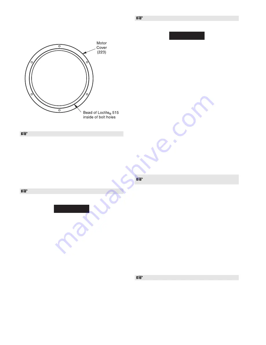
Place cover assembly onto motor housing.
3.
Apply Loctite
®
242 to capscrews (224) and insert into
motor housing. Tighten to 40-50 in lb. (4.5-5.7 Nm).
Motor Cover Sealant Placement
(Dwg. MHP1318)
Mounting Motor To Winch
1.
Assemble exhaust manifold (233) by inserting capscrews
(224) through exhaust manifold and into motor housing.
Tighten to 40-50 in lb. (4.5-5.7 Nm).
2.
Wrap a nylon sling around motor housing and, using a
suitable hoist, slide motor assembly straight onto drive
shaft (61), twisting motor to engage splines on shaft.
3.
Align bolt holes, with air inlet on motor housing facing up.
Insert capscrews (221) through motor flange into adapter
(71) and tighten to 33-36 ft lb. (45-49 Nm).
4.
Attach muffler assembly (234) to exhaust manifold (233).
Control Valve Assembly
Refer to Dwg. MHP1314.
NOTICE
• During assembly align parts using match marks made
during disassembly.
1.
Install seal rings (315) on each end of valve body (316).
2.
Install valve body (316) into valve bushing (314).
3.
Install valve body retainer (305) with two capscrews (302)
and lockwashers (304). Torque capscrews to 25 ft lbs (34
Nm).
4.
Install flange (318) and gasket (317) and secure using
capscrews (302) and lockwashers (304). Torque capscrews
to 25 ft lbs (34 Nm).
5.
If removed, reinstall spring retaining stud (306) and torque
to 25 ft lbs (34 Nm).
6.
Install spring (303) and handle (300) on square shaft of
valve body (316). The spring (303) ends must straddle the
spring retaining stud (306) on throttle handle (300). Install
roll pin (301).
7.
Check throttle handle moves fully left and right without
sticking or binding. Throttle handle should center, by
spring force, automatically when released.
Installation of Control Valve and Inlet Manifold
Refer to Dwg. MHP1314.
NOTICE
• Manifold (606) and cover (607) are bonded together and
thermoplastic coated. If these components are separated then
they must be re-bonded prior to assembly. Refer to the
following:
Bonding Procedure:
a.
Clean mating surfaces of manifold (606) and cover
(607). Apply a thin layer of Loctite
®
515 to one
mating surface.
b.
Insert capscrews (614) through cover. These are just
guides at this time.
c.
Place cover onto manifold. Ensure bolt holes are
aligned. Clamp cover and manifold together and allow
sealant to cure.
d.
Refer to ‘Thermoplastic Coated Parts Assembly’ to
repair removed coating.
1.
Verify spool locating pin (613) is straight and installed in
manifold (606). Position gasket (611) and manifold/cover
assembly on motor housing. Install four capscrews (614) to
clamp parts to motor housing (220). Torque capscrews to
108-112 in lb. (12-13 Nm).
2.
Mount control valve assembly (260) and gasket (321) to
cover such that handle is toward winch drum. Install four
capscrews (331) and torque to 33-36 ft lb. (45-49 Nm).
3.
Connect brake line to swivel elbow fitting (319) on control
valve housing.
4.
Connect air supply line to control valve.
Installation of Remote Control Valve and Inlet
Manifold
Optional feature. Refer to Dwg. MHP1304.
1.
Verify spool locating pin (613) is straight and installed in
manifold (606). Position gasket (611) and manifold on
motor housing. Apply Loctite
®
242 to capscrew (614)
threads and install four capscrews to clamp manifold to
motor housing (220). Torque capscrews to 108-112 in lb.
(12-13 Nm).
2.
Apply Loctite
®
515 to valve assembly mounting surface
and install on cover (607). Apply Loctite
®
242 to capscrew
(615) threads and install four capscrews to clamp cover to
valve assembly. Torque capscrews to 55 ft lb (74 Nm).
3.
Apply Loctite
®
515 to manifold surface and install cover
and valve assembly. Position assembly such that valve
exhaust port is away from the winch drum. Install four
capscrews (608) and torque to 21 ft lb. (28 Nm).
4.
Connect brake line to connector fitting (621).
5.
Connect pendant hoses to valve fittings.
6.
Connect air supply line to control valve.
Emergency Stop Assembly
Optional feature. Refer to Dwg. MHP1331.
1.
Place bracket (527) on bottom of shut off valve (522).
Locate bracket long end on the shut off valve air out side.
Loosely install capscrews (528).
2.
Place bracket (529) on bottom of shut off valve. Locate
bracket face to rear (as viewed from muffler side) of shut
off valve. Install capscrews (531).
3.
Tighten capscrews (528) and (531).
Summary of Contents for FA2A
Page 8: ...7 ...
Page 38: ...37 WINCH CROSS SECTION DRAWING ...
Page 39: ...38 WINCH ASSEMBLY PARTS DRAWING ...
Page 41: ...40 MOTOR ASSEMBLY PARTS DRAWING ...
Page 47: ...46 CONTROL VALVE ASSEMBLY PARTS DRAWING ...
Page 49: ...48 REMOTE PENDANT AND CONTROL VALVE ASSEMBLY PARTS DRAWING ...
Page 53: ...52 EMERGENCY STOP AND OVERLOAD ASSEMBLY PARTS DRAWING ...
Page 55: ...54 REMOTE EMERGENCY STOP AND OVERLOAD ASSEMBLY PARTS DRAWING ...


