41
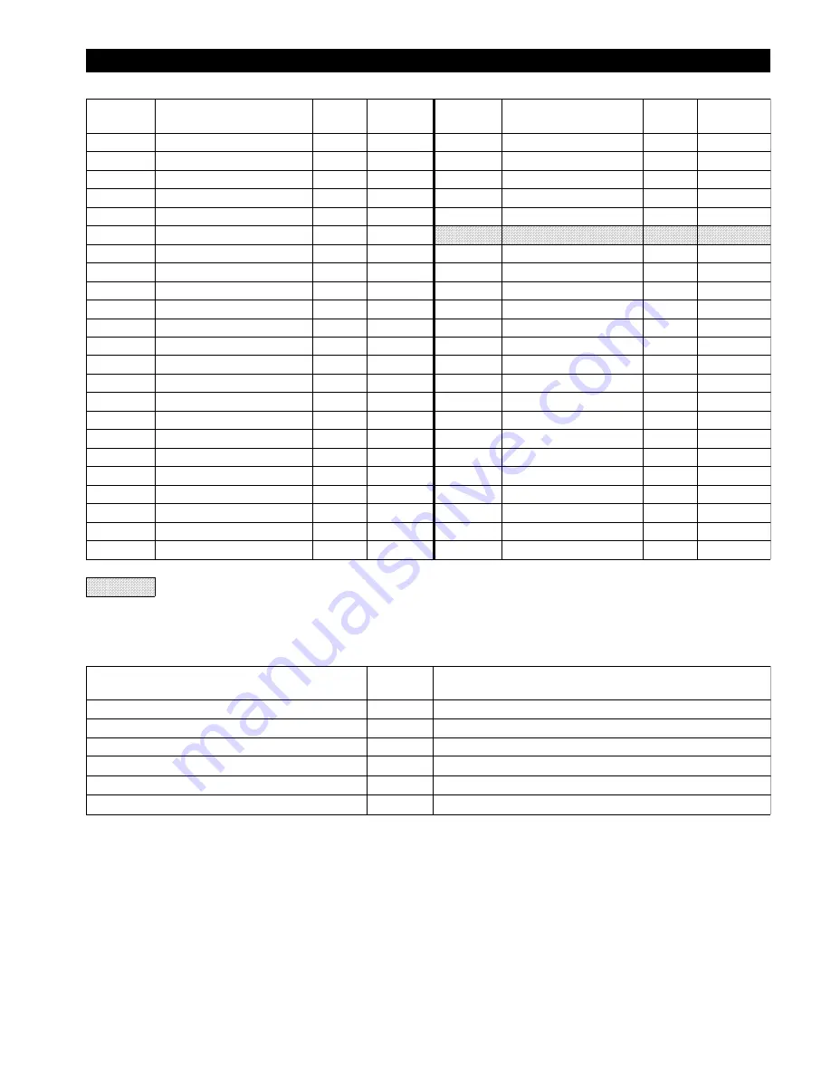
MOTOR ASSEMBLY PARTS LIST
ITEM
NO.
DESCRIPTION
OF PART
QTY
TOTAL
PART
NUMBER
ITEM
NO.
DESCRIPTION
OF PART
QTY
TOTAL
PART
NUMBER
200
Motor Assembly ATPM15
1
26135
224
Capscrew
8
71307292
71
Motor Adapter
1
25445
226
Inboard Cap
2
24971
73
Capscrew
6
54558
227
Outboard Cap
2
24972
74
Washer
6
71304844
228
Cylinder
4
24970
*
202
Locknut
1
71293104
229
Capscrew
16
71307284
*
203
Washer, Tab
1
71293096
•
230
‘O’ Ring
4
71328090
*
204
Bearing (w/retainer)
2
71287114
231
Spool
1
26131-1
*
205
‘O’ Ring
2
71291363
233
Exhaust Manifold
1
25003
*
206
‘O’ Ring
2
51768
234
Muffler Assembly (1)
1
25710
*
207
Ring
2
71287163
235
End Cap, Threaded
1
25711
*
208
Rotary Valve Seal
2
24974
236
Muffler Body Segments
8
25712
*
210
Rotary Valve
1
24973
237
Cap
1
25713
*
211
Pin, Dowel
1
71304851
238
Rod, Threaded
2
25714
*
212
Crankshaft
1
24967
239
Locknut
2
50852
*
213
Pin, Crankshaft
1
24978
240
Piston Assembly
2
25726
214
Counterweight
1
24968
*
241
Piston Rod
2
24962-2
215
Washer
1
71300347
*
242
‘O’ Ring
4
71311773
216
Capscrew
1
71316764
*
243
Piston Sleeve
4
24964-1
217
Locknut
1
71316756
*
244
Link, Rod
2
24966
218
Setscrew
1
71300719
*
245
Bearing
2
71287130
220
Motor Housing
1
23305
*
246
Pin
2
24965
221
Capscrew
4
71306443
*
247
Bearing
2
71287122
223
Motor Cover
1
26134
*
248
Washer
4
71296263
•
Recommended spare.
Notes:
(1)
Muffler Assembly (Item 234) consists of item numbers 235 through 239.
*
Parts not sold separately. Refer to Motor Assembly Kit list.
MOTOR
ASSEMBLY KIT
PART
NUMBER
DESCRIPTION
OF KIT CONTENTS
Cranshaft Assembly Kit
25729
Consists of items 202 through 213 and 245.
Piston Assembly (240)
25726
Consists of items 241 through 248.
Bearing Kit
25725
Consists of items 245 through 248.
Piston Ring Kit
25724
Consists of items 242 and 243.
Inner Cover Assembly Kit
25727
Consists of items 226, 228 and 229.
Outer Cover Assembly Kit
25728
Consists of items 227 through 229.
Summary of Contents for FA2A
Page 8: ...7 ...
Page 38: ...37 WINCH CROSS SECTION DRAWING ...
Page 39: ...38 WINCH ASSEMBLY PARTS DRAWING ...
Page 41: ...40 MOTOR ASSEMBLY PARTS DRAWING ...
Page 47: ...46 CONTROL VALVE ASSEMBLY PARTS DRAWING ...
Page 49: ...48 REMOTE PENDANT AND CONTROL VALVE ASSEMBLY PARTS DRAWING ...
Page 53: ...52 EMERGENCY STOP AND OVERLOAD ASSEMBLY PARTS DRAWING ...
Page 55: ...54 REMOTE EMERGENCY STOP AND OVERLOAD ASSEMBLY PARTS DRAWING ...


