12
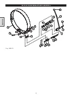
MANUAL BAND BRAKE ASSEMBLY - GENERAL INFORMATION
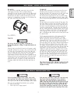
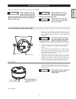
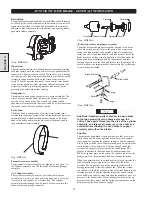
(Dwg. MHP1030)
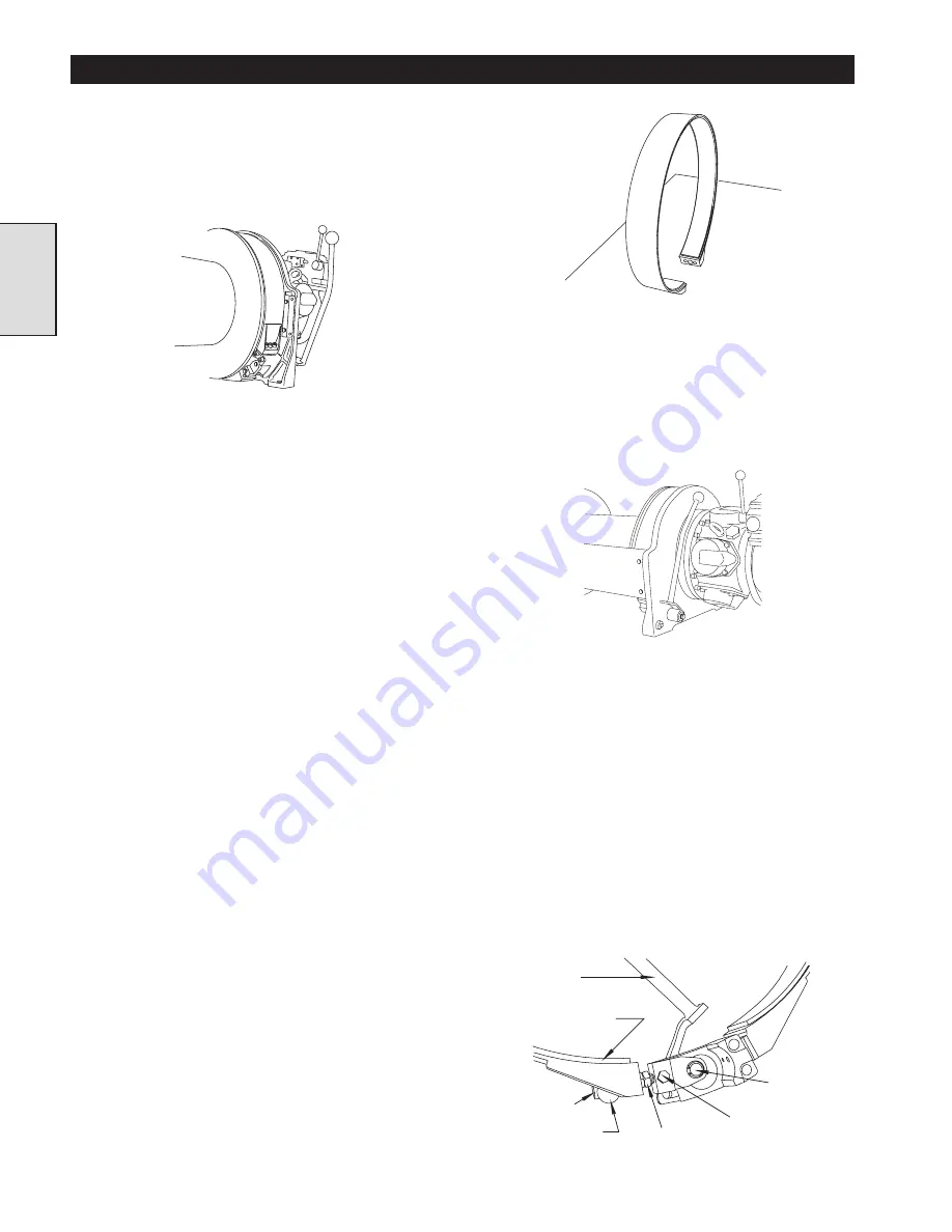
Handle and eccentric assembly
Refer to Dwg. MHP1037
The brake handle has a splined end that engages an eccentric
shaft passing through bearings in an brake bracket which bolts
to the winch upright. There are two needle bearings pressed
into the brake bracket, and are protected from contamination
by ‘O’ rings that act as dirt exclusion seals.
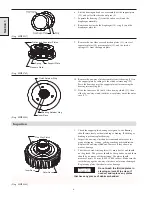
(Dwg. MHP1037)
A cam plate pivots on the end of the eccentric shaft, and this
plate is connected to the free end of the brake band by an
adjustment bolt. The cam plate contains a self lubricating
composite bearing (the sleeve bearing) that allows the cam
plate to pivot freely when the brake is being operated. The
adjustment bolt passes through a pivot bar, and is retained in
the pivot bar by a jam nut that is permanently secured to the
bolt. Turning the jamnut (using an open end wrench) adjusts
the band brake. A locking capscrew acting on a soft bronze
locking pellet prevents the adjustment bolt from turning once
the brake is properly adjusted.
The locking pellet prevents the locking capscrew from
damaging the adjustment bolt when the locking capscrew is
tightened. The pivot bar allows the adjustment bolt to pivot
slightly as the brake is tensioned and released.
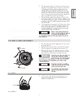
Handle
Brake Band
Friction Lining
Adjustment
Bolt
Pivot Bar
Jam Nut
Locking Capscrew
Eccentric
Shaft
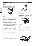
(Dwg. MHP1035)
Description
The optional manual band brake for the FA5A winch is located
on the end of the winch drum next to the air motor. It consists of
a friction material lined steel band (the brake band) that
encircles and grips a brake surface on the winch drum, and a
manually operated engagement and release mechanism.
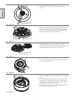
(Dwg. MHP1043)
Operation
The winch operator can engage the brake band at any time,
whether the winch drum is turning in the haul-in direction,
stationary, or turning in the payout direction. Moving the brake
handle towards the winch turns an eccentric shaft which
tensions the brake band, causing it to grip the brake surface and
prevent the winch drum from turning. The handle will “over-
center” and remain in the engaged position until released by the
operator.
To release the manual brake, the operator must pull the handle
away from the winch to the disengaged position allowing the
winch drum to rotate freely. The winch operator needs only to
apply light pressure (about 2.3 to 4.5 kg [5 to 10 pounds]) at the
brake handle to engage the brake and prevent the winch drum
from rotating, and only about 13.6 kg (30 pounds) to move the
handle “over-center” in order to lock the brake in the engaged
position.
The band brake is designed to work more efficiently in the
payout direction than in the haul in direction. Therefore, if the
brake is applied when hauling in, it may not completely stop the
winch drum from turning.
Components
The band brake has two main assemblies. The first assembly
consists of a friction material lined steel band that encircles and
grips the brake surface at one end of the winch drum. The
second assembly is the handle and eccentric assembly that
tensions and releases the band when the winch operator moves
the brake handle.
Function
Brake band
The brake band is composed of a flat steel strip formed into a
circular shape and lined inside with a friction material. Capscrews
threaded through brackets welded to the brake band attach one end
of the band to the eccentric assembly and fasten the other end to an
brake bracket secured to the winch upright.
Section 2
Summary of Contents for FA5A
Page 10: ...10 DISC BRAKE PARTS DRAWING Dwg MHP0667 Dwg MHP0630 One Way Clutch Detail Section 1...
Page 19: ...19 Section 2 SERVICE NOTES...
Page 54: ...54 REDUCTION GEAR ASSEMBLY PARTS DRAWING Dwg MHP1221 Section 5...
Page 57: ...57 SERVICE NOTES...
Page 58: ...58 SERVICE NOTES...
Page 59: ...59 SERVICE NOTES...

