14
Manual Band Brake Removal and Disassembly
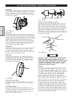
1.
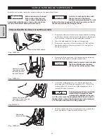
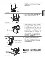
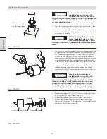
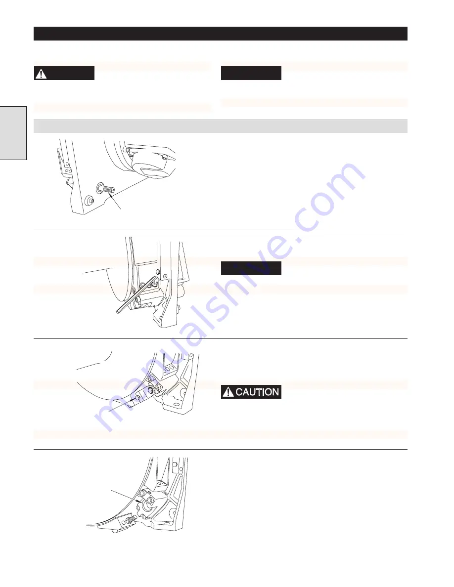
Remove the sideframe closest to the brake assembly by taking
out the four capscrews that fasten the sideframe to the uprights.
This will allow easy access to the band brake assembly.
2.
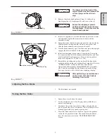
Move the brake handle to the brake release position.
3.
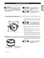
Remove the capscrew (130) and washers (143) that hold the
band brake handle to the eccentric shaft (135), and pull the
handle off the shaft.
(Dwg. MHP1044)
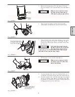
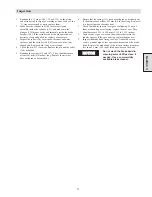
4.
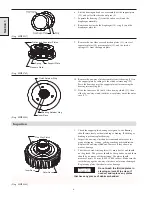
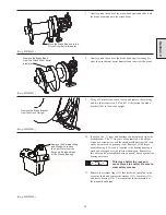
Remove the three capscrews (101) that anchor the stationary
end of the brake band to the brake bracket (106).
NOTICE
Make sure to remove and set aside
the three tubular steel spacers
(103) and the rubber spacer (105).
(Dwg. MHP1036)
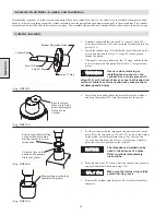
5.
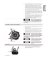
Loosen the locking capscrew (130) and then unscrew the
adjustment bolt (120) from the cam plate (131). (Note: The
locking pellet (129) may fall out if the adjustment bolt is
removed. Retain it for reuse.)
The adjustment bolt is a specially
treated, high strength fastener
permanently attached to the jam
nut. Do not remove the adjustment bolt from the end of
the band brake unless the threads have been damaged,
or if the brake band itself is being replaced.
(Dwg. MHP1041)
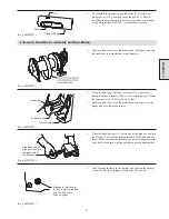
6.
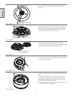
Push the splined end of the eccentric shaft (135) towards the
drum and remove it from the brake bracket (106).
(Dwg. MHP1034)
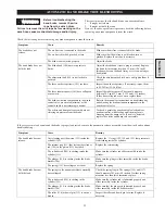
MANUAL BAND BRAKE MAINTENANCE
Read these instructions completely before working on the manual band brake.
Section 2
WARNING
Before working on the band
brake, make sure the wire
rope is slack. Releasing the
band brake while there is a load on the winch can
result in mechanical damage and/or injury.
NOTICE
Service is most easily done with
the motor end of the winch
blocked up approximately 10 cm [4
inches]. Be sure to support the winch securely so that it
cannot move while it is being serviced.
Remove the Brake Handle.
Remove the three
Capscrews holding
the Brake Band to
the Brake Bracket.
Loosen the Locking
Capscrew before removing
the Adjustment Bolt.
Remove the
Eccentric Shaft.
Summary of Contents for FA5A
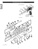
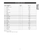
Page 10: ...10 DISC BRAKE PARTS DRAWING Dwg MHP0667 Dwg MHP0630 One Way Clutch Detail Section 1...
Page 19: ...19 Section 2 SERVICE NOTES...
Page 54: ...54 REDUCTION GEAR ASSEMBLY PARTS DRAWING Dwg MHP1221 Section 5...
Page 57: ...57 SERVICE NOTES...
Page 58: ...58 SERVICE NOTES...
Page 59: ...59 SERVICE NOTES...

