29
8.
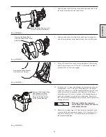
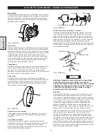
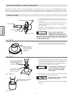
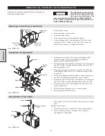
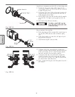
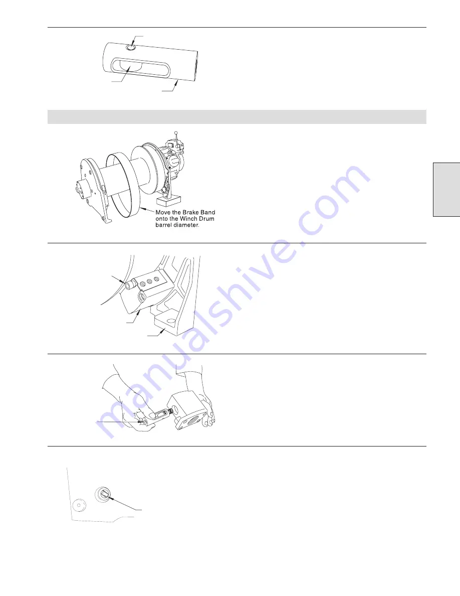
To assemble the plunger, place the roller (116) inside the
plunger body (114), and then insert the pin (115). Before
installing the pin, thoroughly coat the pin, roller, and plunger
with Lubriplate Mo-Lith NO. 2 (or equivalent) grease.
(Dwg. MHP0985)
Automatic Band Brake Assembly and Installation
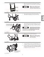
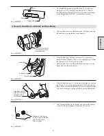
1.
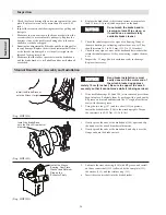
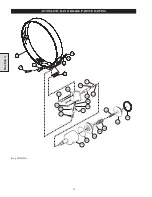
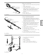
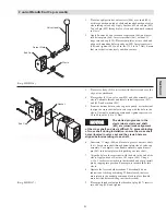
Gently spread the ends of the brake band (104) apart, and slip
the band onto the winch drum barrel diameter.
(Dwg. MHP1097)
2.
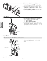
Using the two long (107) and two short (112) capscrews,
fasten the brake bracket (106) on to the winch upright. Torque
the capscrews to 45-50 Nm (33-36 ft. lbs).
3.
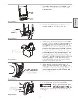
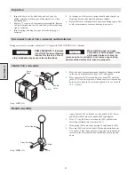
Gently spread the ends of the brake band and slip it over the
flange and onto the brake surface.
(Dwg. MHP1099)
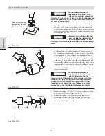
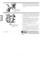
4.
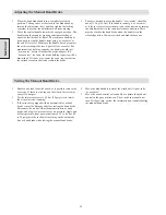
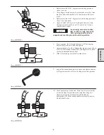
Place the small spring (113) in the end of the plunger, and slip
the plunger (114) into the brake bracket (106) bolted onto the
frame. Make sure that the threaded end of the plunger faces the
open end of the bracket. (Brake bracket pictured unmounted.)
(Dwg. MHP1250)
5.
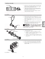
Look through the hole in the upright and position the plunger
so that the slot in the plunger is aligned with the hole.
(Dwg. MHP1032)
Section 3
Pin
Roller
Plunger Body
Brake Bracket
Capscrew
Winch Upright
Threaded end of
Plunger must face
the open end of
the Bracket.
Make sure that the slot
in the Plunger is lined up
with the hole in the
Winch Upright.
Summary of Contents for FA5A
Page 10: ...10 DISC BRAKE PARTS DRAWING Dwg MHP0667 Dwg MHP0630 One Way Clutch Detail Section 1...
Page 19: ...19 Section 2 SERVICE NOTES...
Page 54: ...54 REDUCTION GEAR ASSEMBLY PARTS DRAWING Dwg MHP1221 Section 5...
Page 57: ...57 SERVICE NOTES...
Page 58: ...58 SERVICE NOTES...
Page 59: ...59 SERVICE NOTES...

