30
6.
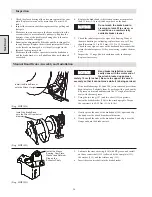
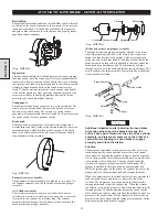
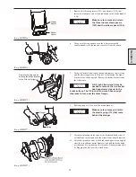
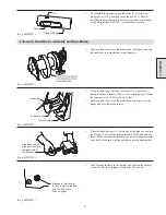
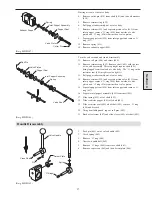
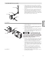
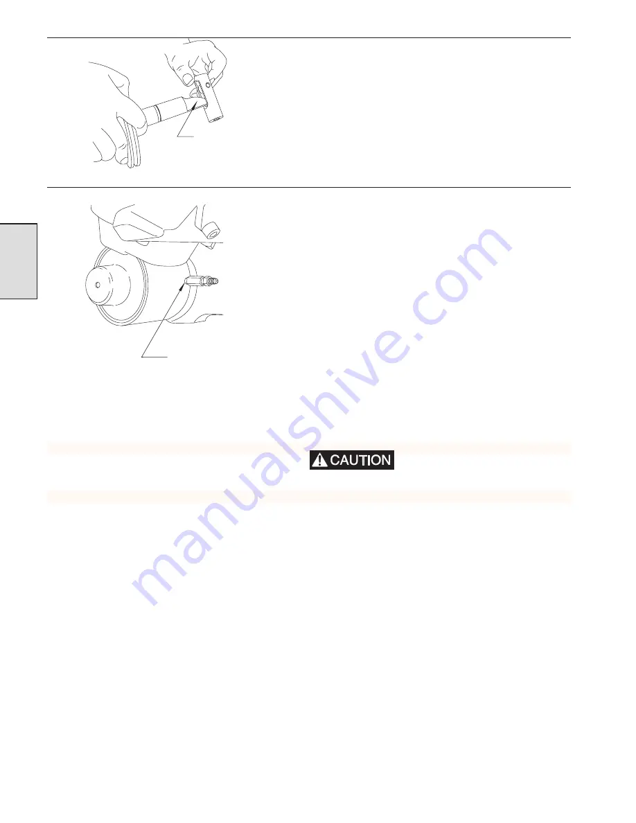
Position the cylinder rod (inside the plunger) with the cam
shaped side against the roller, and then screw the threaded end
of the cylinder assembly through the hole in the sideframe into
the bracket. (Cylinder rod and plunger are shown disassembled
for clarity.)
(Dwg. MHP1039)
7.
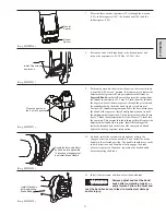
Thread the cylinder fully (until snug) into the side frame, and
then back off until the threaded hole in the side of the cylinder
is pointed towards the air motor and is positioned horizontally.
8.
Install the dump valve and orifice assembly on the cylinder,
and connect the air line.
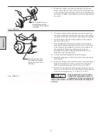
9.
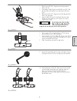
If the adjustment bolt lock nuts have been removed, apply
some thread-locking compound (Loctite® 680 or equivalent)
to the threads of the adjustment bolt close to the shank (near
the brake band). Thread one of the lock nuts onto the
adjustment bolt so that it holds the adjustment bolt on the
brake band with very little slack.
10. Loosely thread the adjustment bolt into the plunger.
11. Install the rubber spacer (105) between the brake band and the
brake bracket.
12. Fasten the stationary end of the brake band to the brake bracket
using the three capscrews (101), washers (102) and spacer
(103). Torque the capscrews to 45-50 Nm (33-36 ft lbs).
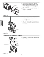
13. Fasten the corner bar to the winch upright, and torque the two
capscrews to 45-50 Nm (33-36 ft lbs). Install the sideframe and
torque the four capscrews to 72-78 Nm (52-57 ft lbs).
Always adjust and test the band
brake after completing repairs or
adjustments. Failure to adjust and
test the band brake can lead to mechanical damage and/
or injury.
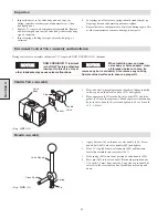
(Dwg. MHP1251)
Section 3
The Cylinder Rod must
be positioned with the
Cam shaped side against
the Roller.
Position threaded hole
horizontally and install
Dump Valve and Orifice
Assembly.
Summary of Contents for FA5A
Page 10: ...10 DISC BRAKE PARTS DRAWING Dwg MHP0667 Dwg MHP0630 One Way Clutch Detail Section 1...
Page 19: ...19 Section 2 SERVICE NOTES...
Page 54: ...54 REDUCTION GEAR ASSEMBLY PARTS DRAWING Dwg MHP1221 Section 5...
Page 57: ...57 SERVICE NOTES...
Page 58: ...58 SERVICE NOTES...
Page 59: ...59 SERVICE NOTES...

