34
34
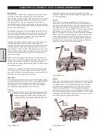
DIRECTIONAL CONTROL VALVE - GENERAL INFORMATION
Description
The air winch is controlled by a poppet type directional control
valve that is either lever operated at the winch or pendant
operated from a remote location. The winch operator can control
the winch drum direction and speed by moving a lever on the
winch control valve or by pressing a button on the remote
pendant. Materials used in the construction of the valve include
cast iron for the body, with corrosion resistant stainless steel and
bronze for the internal parts.
The poppets are designed for zero air leakage when the valve is
in the neutral position, and precise control of the air flow when
the valve is operated. Inlet air pressure provides a balancing
force on each inlet poppet to enhance control and reduce the
lever force on manually operated valves.
Incorporated in the directional control valve are an exhaust air
restrictor and a brake release valve for winches that are
equipped with a disc brake. The exhaust air restrictor allows the
winch operator to control the winch payout speed with the air
motor instead of using the brake. The brake release valve causes
the disc brake to release when the directional control valve lever
is moved or the pendant button is pressed to run the winch in
the payout direction.
When a winch is equipped with an automatic band brake, two
brake release valves are installed in the control valve. One valve
releases the band brake when the lever moves to the haul-in
position and one releases the band brake when the handle moves
to the payout position.
A shuttle valve, mounted on a block on the directional control
valve body, causes the brake release valve to release both the
band and disc brake in the payout direction, and causes only the
band brake to release in the haul-in direction.
Operation
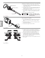
The manual control lever pivots on a cross shaft running through
an end cap bolted to the valve body. The lever is spring loaded so
that the control valve returns and automatically locks into the
neutral position. A clevis attached to the cross shaft engages a
control shaft that runs lengthwise in the valve body.
Neutral
When the manual control lever is in the neutral position, no air is
admitted into the winch motor and the winch brake(s)
remains engaged. To run the winch, the directional
control valve lever must first be manually lifted and
Section 4
then moved towards or away from the operator. This action
causes the control shaft to open the appropriate poppets and admit
air to the winch motor.
Payout
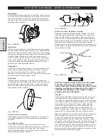
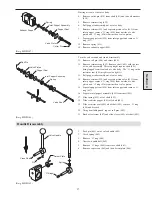
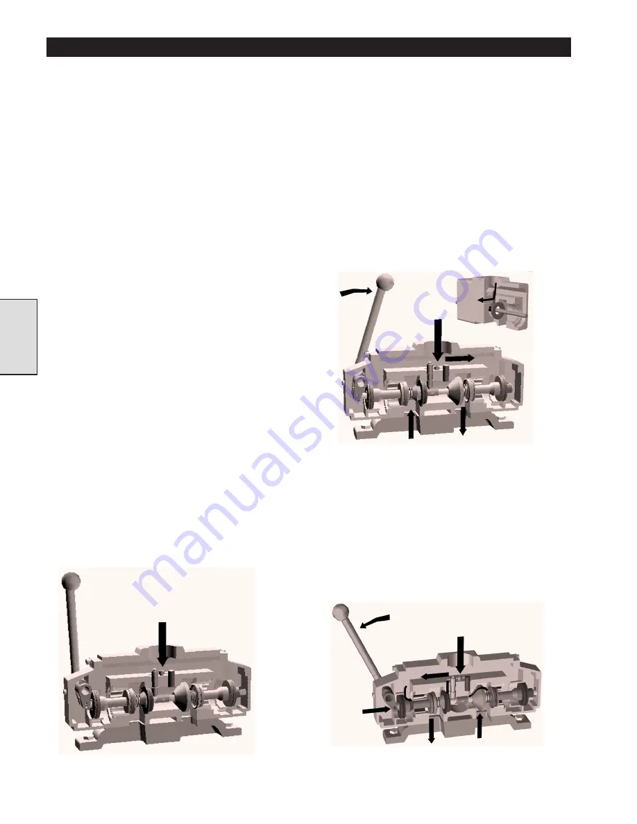
When the winch operator manually moves the directional
control valve lever to the right (when viewed from the motor
end), the control shaft slides to the left and causes the right hand
inlet poppet and the left hand exhaust poppet to open at the
same time. Refer to drawing MHP1186. The inlet poppet admits
high pressure air into the motor, and the exhaust restrictor
poppet controls the air leaving the motor through the secondary
exhaust port. This restriction regulates the payout speed of the
winch, reducing brake use and increasing operator control of
descending loads. If the winch is equipped with an automatic
disc and/or band brake, a sleeve on the valve shaft activates a
brake release valve(s) that release the brake(s).
(Dwg. MHP1186)
Haul-in
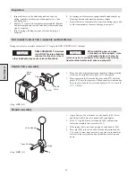
When the winch operator moves the manual control lever to the
left (when viewed from the motor end), the valve shaft slides to
the right and causes the left hand inlet poppet valve and the
right hand exhaust restrictor poppet to open at the same time.
Refer to drawing MHP1185. The inlet poppet admits high
pressure air into the motor, and the exhaust poppet allows air to
leave the motor through the secondary exhaust port. If the winch
is equipped with an automatic band brake only, a sleeve on the
valve shaft activates a brake release valve.
(Dwg. MHP1185)
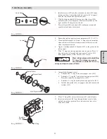
Neutral
Position
Payout
Position
Haul-in
Position
(Dwg. MHP1184)
Summary of Contents for FA5A
Page 10: ...10 DISC BRAKE PARTS DRAWING Dwg MHP0667 Dwg MHP0630 One Way Clutch Detail Section 1...
Page 19: ...19 Section 2 SERVICE NOTES...
Page 54: ...54 REDUCTION GEAR ASSEMBLY PARTS DRAWING Dwg MHP1221 Section 5...
Page 57: ...57 SERVICE NOTES...
Page 58: ...58 SERVICE NOTES...
Page 59: ...59 SERVICE NOTES...

