38
Inspection
4.
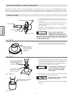
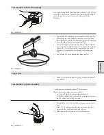
Set springs on a flat surface, springs should stand straight up.
If springs have any abnormal appearance, replace.
5.
Ensure that valve components are kept clean during repair. Dirt
or other contaminates can cause damage to new parts.
Directional Control Valve Assembly and Installation
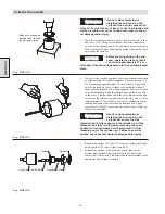
During control valve assembly lubricate all ‘O’ rings with DOW CORNING #111 lubricant.
NOTICE
When installing new end caps,
valve body or valve adapter, clean
all threaded holes with a tap (to
remove any burrs or debris). Also remove any coating
from machined surfaces to ensure a proper fit.
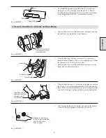
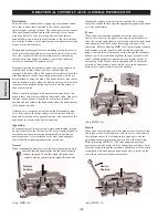
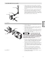
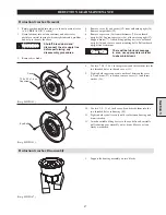
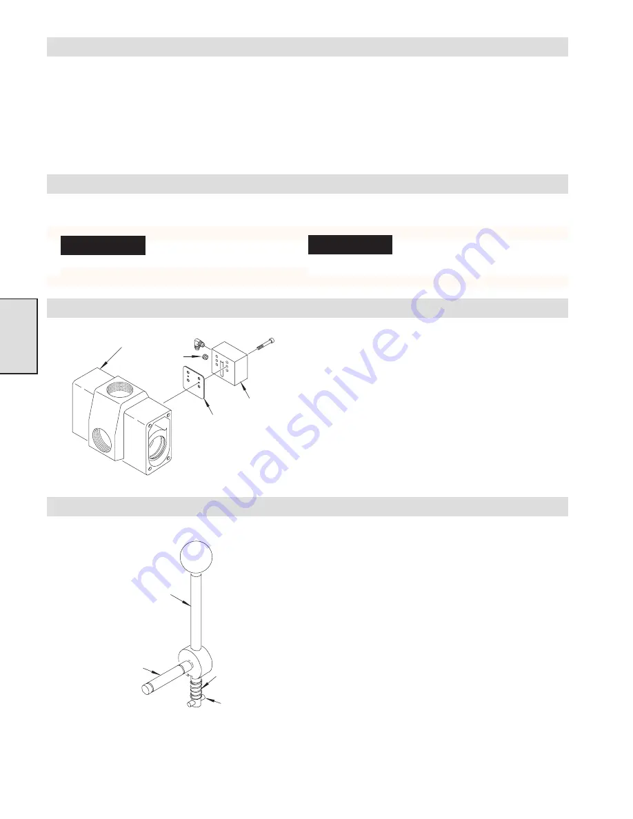
Shuttle Valve Assembly
1.
Place a bead of pipe sealant around threads of fittings installed
in lower port on shuttle valve body (479) and tighten.
2.
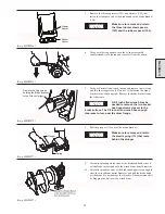
Place capscrews (418) into shuttle valve body(479) and slide
gasket (419) onto the capscrews. Match capscrews to mounting
holes in valve body (410) insert and tighten to 24 to 30 inch lb.
(8.9 - 3.0 Nm).
(Dwg. MHP1150)
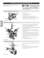
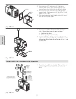
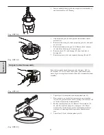
Handle Assembly
1.
Apply Loctite
®
242 on threads of valve handle (449). Screw
handle ball (469) onto valve handle (449) and tighten.
2.
Slide ‘O’ ring (460) onto valve handle (449) and lubricate.
Insert this assembly into cross shaft (461).
3.
Slide spring (462) onto lower portion of valve handle (449).
4.
Press pin (463) into valve handle. Pin should protrude about
1/16 inch (1.6 mm) from one side. Long side of pin should fit
into slot in the cross shaft and not bind when moved up and
down.
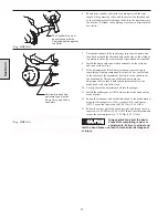
(Dwg. MHP1151)
Section 4
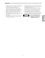
1.
Inspect the bores in the valve body and end caps, for
pitting, scratches or other signs of abnormal wear. Clean
and lightly hone.
2.
Replace ‘O’ rings in all components disassembled. Replace
any steel components (not the valve body) that are showing
sign of corrosion.
3.
Inspect springs, looking for signs of cracks, bulging, or
corrosion.
NOTICE
DOW CORNING #111 lubricant
is the ONLY factory authorized
lubricant for this valve. Use of
other lubricants may cause valve malfunctions.
Valve
Body
Plug
Gasket
Shuttle
Valve
Valve Handle
Cross Shaft
Spring
Pin
Summary of Contents for FA5A
Page 10: ...10 DISC BRAKE PARTS DRAWING Dwg MHP0667 Dwg MHP0630 One Way Clutch Detail Section 1...
Page 19: ...19 Section 2 SERVICE NOTES...
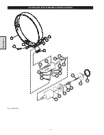
Page 54: ...54 REDUCTION GEAR ASSEMBLY PARTS DRAWING Dwg MHP1221 Section 5...
Page 57: ...57 SERVICE NOTES...
Page 58: ...58 SERVICE NOTES...
Page 59: ...59 SERVICE NOTES...


