4
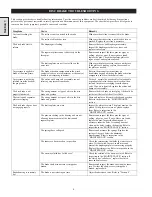
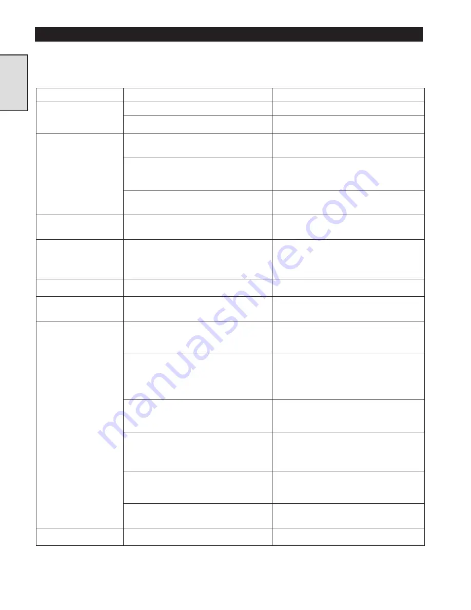
This section provides basic troubleshooting information. Specific causes to problems are best identified by thorough inspections
performed by personnel instructed in safety, operation and maintenance of this equipment. The chart below provides a brief guide to
common disc brake symptoms, probable causes and remedies.
DISC BRAKE TROUBLESHOOTING
Section 1
Symptom
Cause
Remedy
Air is not reaching the
brake.
The air line is not connected to the brake.
Make sure the air line is connected to the brake.
The air line is blocked or torn.
Make sure that the air line is not blocked, torn or
pinched. Replace the air line if necessary.
The disc brake fails to
release.
The diaphragm is leaking.
Remove the cover and diaphragm assembly.
Inspect the diaphragm for holes or tears, and
replace if necessary.
The separator plates cannot slide freely on the
three pins.
Remove and inspect the three pins for signs of
galling, ridges or wear. If any signs are found,
replace the pins. Check the separator plates for
signs of wear and replace as needed.
The friction plates are not free to slide on the
outer race.
Make sure the plates are free to move on the race.
If the plates are sticking, replace the race and/or
the plates as needed.
Air pressure is applied to
brake at the wrong time.
The brake activation components in the winch
control valve are out of adjustment, or the control
handle is not returning to neutral.
Refer to the manual for instructions on
troubleshooting and adjusting the brake activation
components and the winch control valve.
Air pressure is not being
released from the brake at
the proper time.
The orifice and dump valve assembly are not
relieving air pressure from brake.
To check, operate the winch control valve handle
or pendant control in the pay-out direction, then
feel and listen for air escaping from the dump
valve. If no air is detected, replace the orifice and
dump valve assembly.
The disc brake is not
properly lubricated.
The wrong amount or type of oil is in the disc
brake and gearbox.
Remove the disc brake oil level plug. Oil should be
just below the level of the oil level hole.
The friction and separator
plates are slipping.
The wrong amount or type of oil is in the disc
brake and gearbox.
Drain and replace oil from disc brake and gearbox.
Refer to inspection in the “MAINTENANCE”
section.
The disc brake slips or does
not engage properly.
The friction plates are worn.
Inspect the plates for wear. The plates must not be
glazed. If the plates are worn or glazed, replace
them. Refer to inspection in the
“MAINTENANCE” section.
The pins are sticking in the housing and are not
allowing free movement of the friction and
separator plates.
Remove and inspect the three pins for signs of
galling, ridges or wear. If any of these are found,
replace the pins. Inspect the housing and if
necessary ream the holes. If reaming does not
clean up the holes, replace the housing. Refer to
inspection in the “MAINTENANCE” section.
The springs have collapsed.
Remove and measure the springs. Replace the
springs if they are below the minimum
measurement. Refer to inspection in the
“MAINTENANCE” section.
The inner race has moved out of position.
Check the retainer ring that holds the inner race in
place. If it has failed, the race could move and
prevent the diaphragm plate from moving properly.
Replace the retainer ring. Refer to inspection in the
“MAINTENANCE” section.
The one-way clutch has "rolled over".
Check the rotation of the one-way clutch. Refer to
inspection in the “MAINTENANCE” section. If
the clutch has "rolled over" replace the clutch,
inner and outer races.
The brake shaft or inner race is stripped or
broken.
Remove and inspect the brake shaft and the inner
race. If either the shaft or race is stripped or
broken, replace both.
Brake housing is extremely
hot.
The brake is not releasing on time.
Adjust brake release valve. Refer to “Section 4”.
Summary of Contents for FA5A
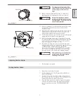
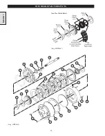
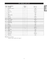
Page 10: ...10 DISC BRAKE PARTS DRAWING Dwg MHP0667 Dwg MHP0630 One Way Clutch Detail Section 1...
Page 19: ...19 Section 2 SERVICE NOTES...
Page 54: ...54 REDUCTION GEAR ASSEMBLY PARTS DRAWING Dwg MHP1221 Section 5...
Page 57: ...57 SERVICE NOTES...
Page 58: ...58 SERVICE NOTES...
Page 59: ...59 SERVICE NOTES...

