43
2.
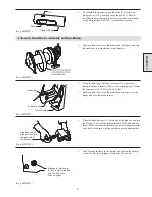
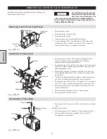
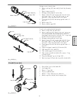
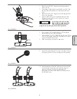
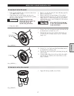
Rotate sleeve (408) 180º (degrees) or until long portion of
sleeve is on top.
3.
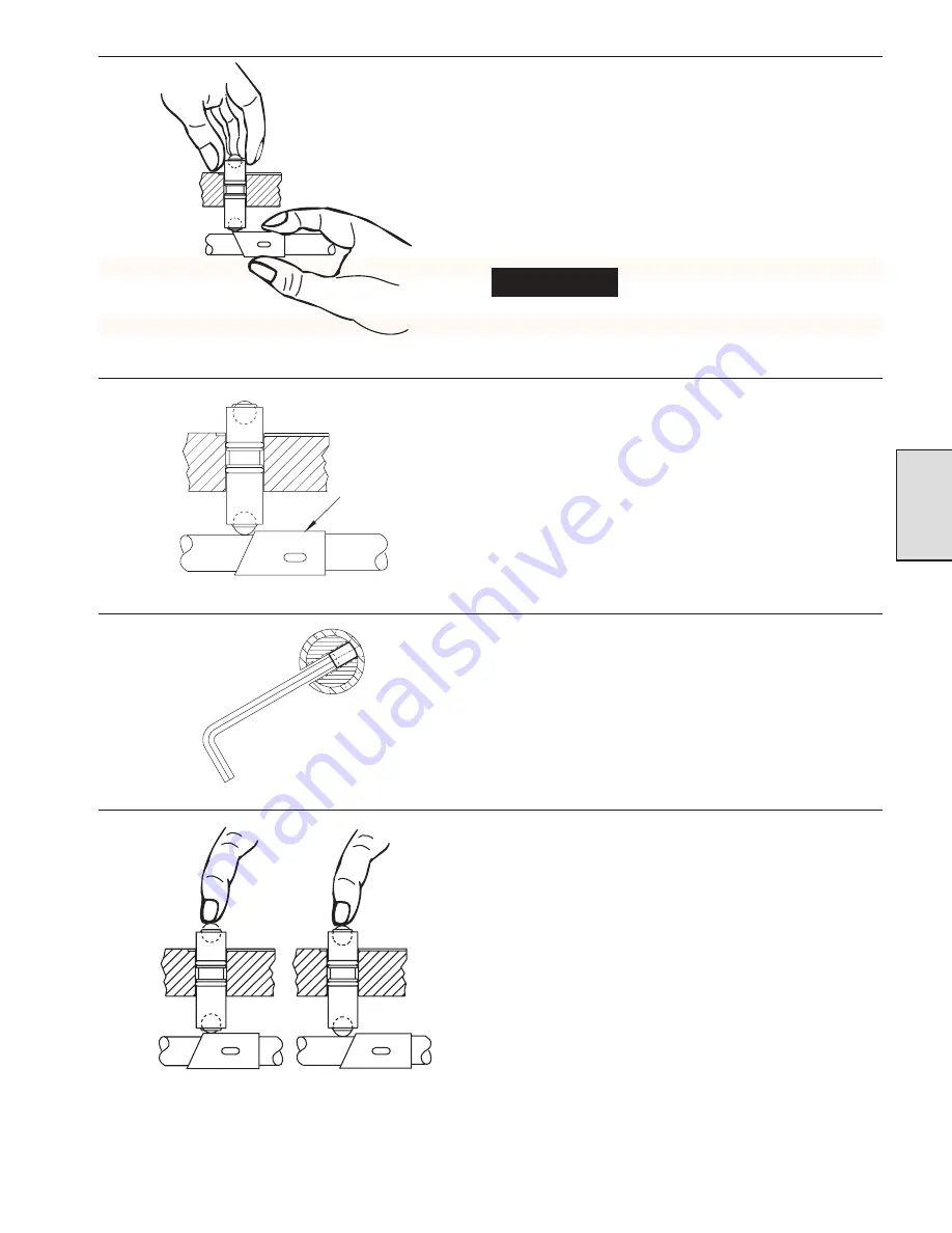
Using fingers on the brass body, press brake valve (413) into
the valve body until steel ball is in firm contact with sleeve
(408).
4.
Rotate sleeve (408) 180º (degrees) or until the long portion of
sleeve is on the bottom.
5.
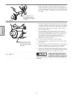
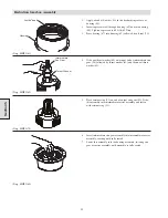
Apply Loctite® 609 to pin (412) and push into valve body
(through air inlet) until 0.16 to 0.25 inch (4 to 6.5 mm) is
exposed above surface.
NOTICE
Avoid using excessive Loctite
®
609. Loctite can drip onto shaft
(401) causing shaft to stick in
poppet seat, resulting in erratic winch operation.
(Dwg. MHP1024)
6.
Insert capscrew (465) through flatwasher (417) and spring
retainer (416) into valve body and tighten.
7.
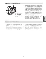
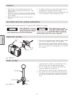
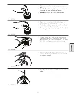
Adjusting brake valve (413). Ensure that long portion of sleeve
(408) is on the bottom of shaft (401) and align a slot in sleeve
with center threaded hole in shaft.
8.
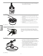
Slide sleeve fully up to steel ball in brake valve.
(Dwg. MHP1027)
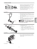
9.
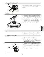
Insert allen wrench through slot in sleeve and tighten setscrew
(407) against far side of sleeve. Locking sleeve into position.
(Dwg. MHP1025)
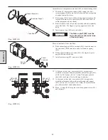
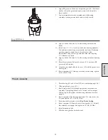
10. Check operation of brake valve. Press control lever assembly
to the front (haul-in) position at the same time using your
finger to feel the top steel ball. The ball should rise
immediately. When the control handle is returned to neutral,
the ball should drop.
(Dwg. MHP1026)
Section 4
Sleeve
Summary of Contents for FA5A
Page 10: ...10 DISC BRAKE PARTS DRAWING Dwg MHP0667 Dwg MHP0630 One Way Clutch Detail Section 1...
Page 19: ...19 Section 2 SERVICE NOTES...
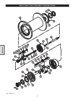
Page 54: ...54 REDUCTION GEAR ASSEMBLY PARTS DRAWING Dwg MHP1221 Section 5...
Page 57: ...57 SERVICE NOTES...
Page 58: ...58 SERVICE NOTES...
Page 59: ...59 SERVICE NOTES...

