45
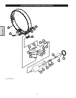
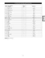
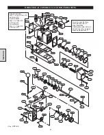
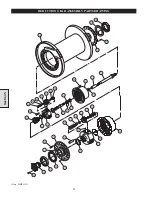
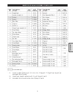
DIRECTIONAL CONTROL VALVE PARTS LIST
Section 4
ITEM
NO.
DESCRIPTION
OF PART
QTY
TOTAL
PART
NUMBER
ITEM
NO.
DESCRIPTION
OF PART
QTY
TOTAL
PART
NUMBER
400
Valve Assembly *
1
- - -
428
Poppet Seat
2
23518
Single Air Brake
24801
429
Retainer Ring
2
53833
Single Air Brake - CE *
25451
430
‘O’ Ring
2
52573
Dual Air Brakes
24803
431
Valve Piston
2
23519
Dual Air Brakes - CE *
25442
432
Retainer Ring
2
71138010
Without Air Brakes
24804
433
Washer
8
71271985
Without Air Brakes - CE *
25443
434
Washer
†
53881
401
Valve Shaft
1
23522
435
Plug
‡
71069009
402
Restrictor, Poppet
1
23523
436
Plug
1
71303689
403
Restrictor, Seat
1
23524
437
Capscrew
4
71138069
404
‘O’ Ring
1
71137988
438
Valve Cap
1
23520
405
Pin
2
71293179
439
Capscrew
4
71138077
406
Pin
1
71293161
440
Adapter, Standard
1
23514
407
Setscrew
1
71138093
Adapter, CE
24373
408
Sleeve
1
23606
441
Capscrew
4
71138085
409
Pin
1
71149157
442
Capscrew
4
53890
410
Valve Body
1
24795
443
Label, Standard
1
71148290
411
Gasket
2
23592
Label, CE
96180102
412
Pin
**
71146195
444
Shim
†
71138119
413
Valve Assembly
**
23594
445
Pin
1
71145379
‘O’ Ring (each assembly)
2
446
Clevis
1
23589
414
Pin, Cotter
1
71287478
447
Plug
1
25498
416
Spring Clip
1
24793
448
‘O’ Ring
2
71137962
417
Washer
1
50899
449
Handle
1
23747
418
Capscrew
2
71261747
450
Valve Cap
1
23607
419
Gasket
1
23744
460
‘O’ Ring
1
71146963
420
Exhaust Poppet
1
23516
461
Cross Shaft
1
23746
421
Plug
1
51897
462
Spring
1
71146948
422
Spring
2
71138028
463
Pin
1
71146955
423
Inlet Poppet Assembly
2
24139
464
Detent Plate
1
23748
424
Gasket
1
71264725
465
Capscrew
3
53807
425
Fitting, Elbow
‡
71262299
469
Knob
1
71138051
426
‘O’ Ring
2
52662
470
Capscrew
2
71303671
427
‘O’ Ring
2
51768
471
Seal Washer
2
71303838
479
Shuttle Valve Body
1
23739
Recommended spare.
*
Valve Assembly (Item 400) consists of Items 401 through 417, 420 through 424, 426 through 434 and 436 through 471.
** Refer to the following to determine Pin (Item 412) and Valve Assembly (Item 413) configuration requirements:
1. Winches without disc or automatic drum band brake (Valve Assemblies 24804 or 25443) use quantity of 2 Pins (Item 412).
2. Winches with a single automatic brake (disc or drum band) (Valve Assemblies 24801 or 25451) use quantity of 1 Pin (Item
412) and quantity of 1 Valve Assembly (Item 413).
3. Winches with disc and automatic drum bank brakes (Valve Assemblies 24803 or 25442) use quantity of 2 Valve Assemblies
(Item 413).
†
Quantity of 4 Washers (Item 434) required to mount Adapter (Item 440). Additional Washer (Item 434) and Shim (Item 444)
quantities = ‘As Required’ to establish clearance tolerances described in “MAINTENANCE” section.
‡
Refer to Dwg. MHP0764 to determine Shuttle Valve (Item 479) configuration.
•
•
•
•
•
•
•
•
•
•
•
•
•
•
Summary of Contents for FA5A
Page 10: ...10 DISC BRAKE PARTS DRAWING Dwg MHP0667 Dwg MHP0630 One Way Clutch Detail Section 1...
Page 19: ...19 Section 2 SERVICE NOTES...
Page 54: ...54 REDUCTION GEAR ASSEMBLY PARTS DRAWING Dwg MHP1221 Section 5...
Page 57: ...57 SERVICE NOTES...
Page 58: ...58 SERVICE NOTES...
Page 59: ...59 SERVICE NOTES...

