53
8.
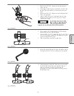
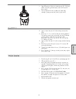
Apply EP grease to the end of output sun gear (45). Set thrust
washer (43) in the grease and apply more to the top of the
thrust washer.
9.
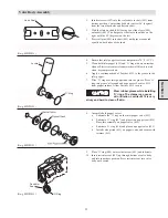
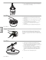
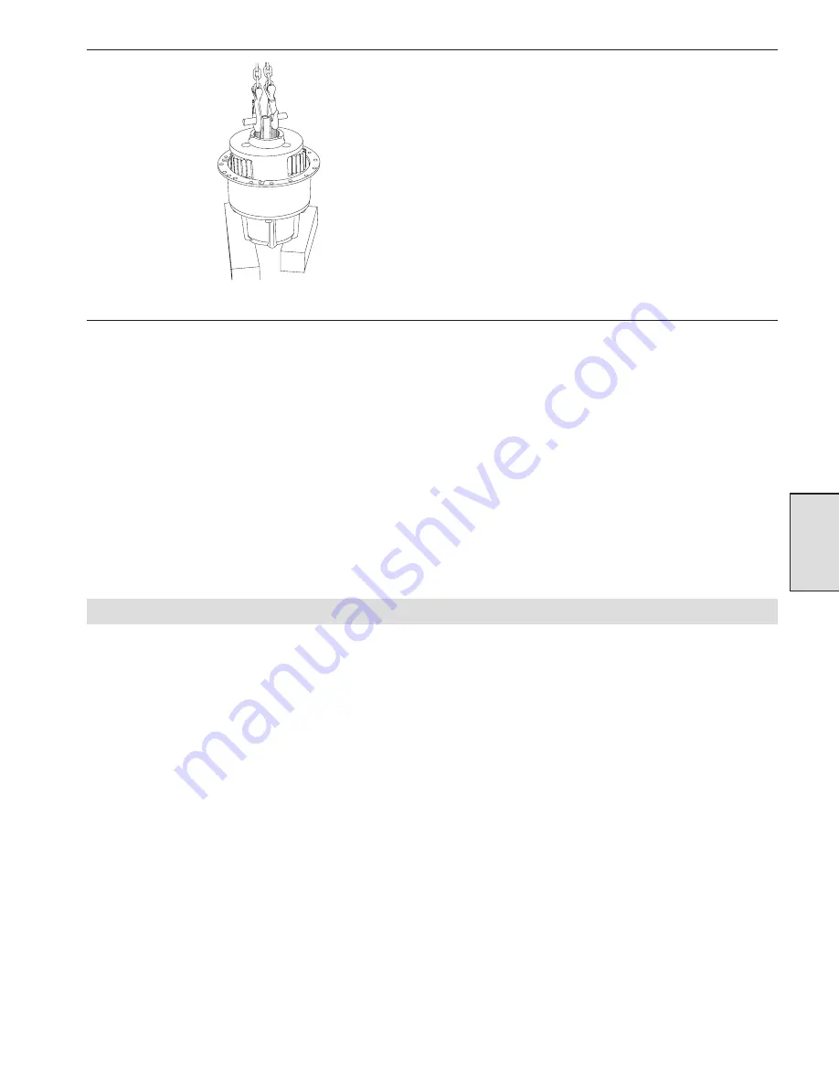
Lower intermediate carrier assembly into the housing
assembly, twisting carrier until carrier is fully seated.
(Dwg. MHP11688)
10. Apply a bead of Loctite
®
515 to the mating surface of the
drum.
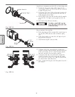
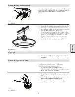
11. Install two 1/2 - 13 x 1 inch eye bolts into housing assembly.
Lift and insert reduction gear assembly into drum. Reduction
gearbox assembly might have to be rotated to allow
intermediate sun gear to align with and slide into coupling
(73). Remove eye bolts.
12. Apply a bead of Loctite
®
515 to the mating surface of housing
(44).
13. Place thrust washer (36) inside of cover (33), use some EP
grease to hold in place.
14. Align the two threaded holes in cover (33) with the grooves in
housing (44).
15. Insert capscrews (32) through cover and into housing, tighten
to 60 ft lb (81 Nm).
Winch Assembly
1.
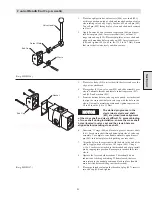
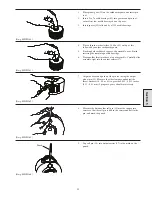
Press bearing (30) and oil seal (29) into outboard upright (26).
2.
Slide upright onto cover (33).
3.
Insert output shaft (28) through upright and into reduction
assembly. Upright might have to be rotated to allow output
shaft to align with splines in reduction gearbox and teeth in
upright.
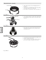
4.
Insert capscrews (86) through sideframe (78), into corner bar
(20) and tighten to 75 ft lb (102 Nm).
5.
For units with disc brake refer to Disc Brake Section.
6.
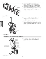
Insert capscrew (2) through cover (4) and gasket (19). Install
this assembly on upright and tighten to 18 ft lb (24 Nm).
7.
Install mounting bolts.
8.
Fill reduction gearbox with lubricant.
Section 5
Summary of Contents for FA5A
Page 10: ...10 DISC BRAKE PARTS DRAWING Dwg MHP0667 Dwg MHP0630 One Way Clutch Detail Section 1...
Page 19: ...19 Section 2 SERVICE NOTES...
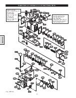
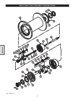
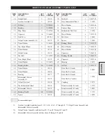
Page 54: ...54 REDUCTION GEAR ASSEMBLY PARTS DRAWING Dwg MHP1221 Section 5...
Page 57: ...57 SERVICE NOTES...
Page 58: ...58 SERVICE NOTES...
Page 59: ...59 SERVICE NOTES...

