6
6.
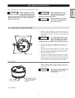
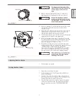
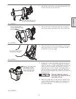
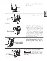
Lift the housing and end cover assembly off the support plate
(22), and collect the three dowel pins (8).
7.
Separate the housing (7) from the end cover (4) and the
diaphragm assembly.
8.
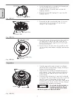
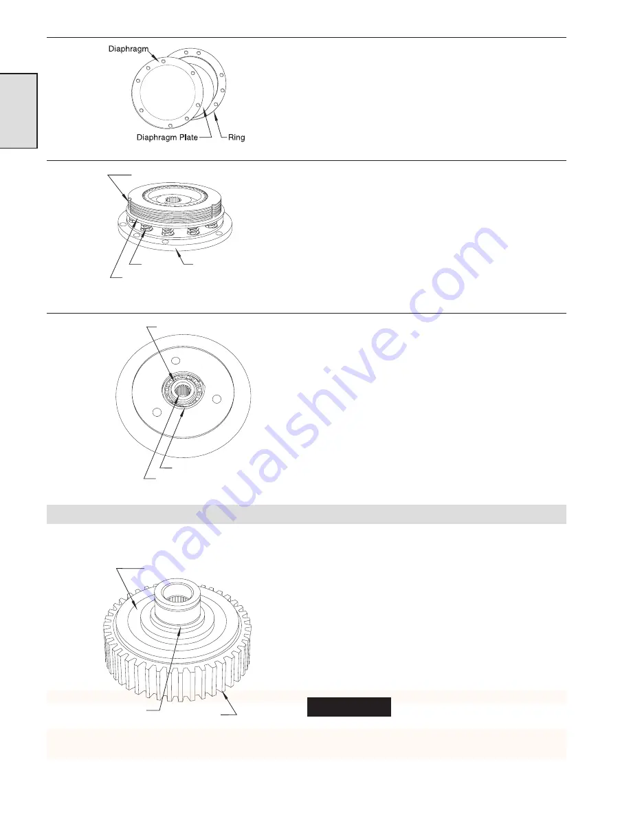
Remove and set aside the diaphragm (10), ring (5), and the
diaphragm plate (6).
(Dwg. MHP0837)
9.
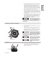
Remove the five fiber covered friction plates (13), six steel
separator plates (14), pressure plate (12), and the twelve
springs (21) from the support plate.
(Dwg. MHP0769)
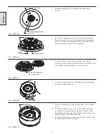
10. Remove the one-way clutch assembly from its bearing (23) in
the support plate by taking off the clutch retainer ring (25).
Press the bearing out of the support plate after removing the
bearing retainer ring (24).
11. Slide the inner race (16) out of the one-way clutch (11), then
slide the one-way clutch (with the wear plates) out of the outer
race (17).
(Dwg. MHP0845)
Inspection
1.
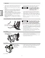
Check the support plate bearing for signs of wear. Bearing
should rotate freely without sticking or binding. If sticking or
binding is present replace bearing.
2.
Inspect the one-way clutch and its inner and outer races for
signs of slipping, scoring, galling, cracking or discoloration.
Replace the one-way clutch and the races if they show any
wear or damage.
3.
The fiber covered friction plates (13) must be flat, and should
not be glazed. The grooves should be sharp and even, and there
should be no pieces of fiber missing. The plates should
measure 2 mm ±0.1 mm (0.080 ±0.004 inches). Make sure the
teeth that engage the one-way clutch are not worn or damaged.
Replace any plates that show wear or damage.
NOTICE
Do not wash the friction plates in
cleaning solvent. Wipe clean if
needed, and replace any plates
that have any pieces of debris embedded.
(Dwg. MHP0848)
Section 1
Inner Race
Outer Race
One Way Clutch
Friction and Separator Plates
Pressure Plate
Spring
Support Plate
Bearing Retainer Ring
Inner Race
Clutch Retainer Ring
Summary of Contents for FA5A
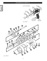
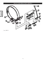
Page 10: ...10 DISC BRAKE PARTS DRAWING Dwg MHP0667 Dwg MHP0630 One Way Clutch Detail Section 1...
Page 19: ...19 Section 2 SERVICE NOTES...
Page 54: ...54 REDUCTION GEAR ASSEMBLY PARTS DRAWING Dwg MHP1221 Section 5...
Page 57: ...57 SERVICE NOTES...
Page 58: ...58 SERVICE NOTES...
Page 59: ...59 SERVICE NOTES...

