9
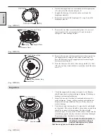
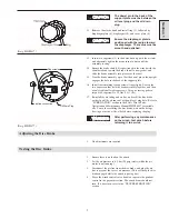
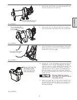
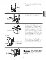
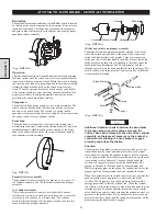
The dowel pin in the back of the
support plate must be between the
oil level plug and the oil drain
plug.
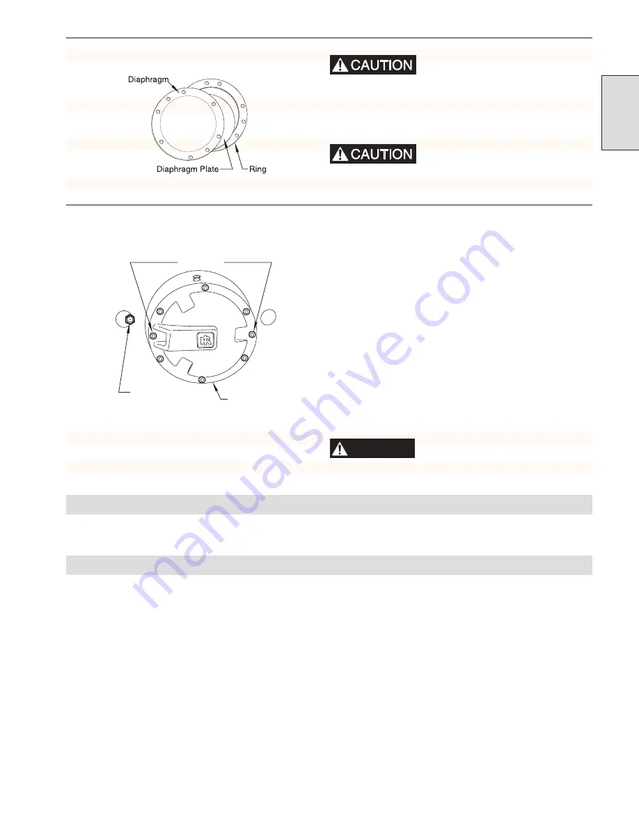
12. Remove the elastic band and install ring (5), followed by
diaphragm plate (6), diaphragm (10), and cover plate (4).
Ensure the diaphragm plate is
positioned with the radius toward
the diaphragm. The radius must be
smooth and polished.
(Dwg. MHP0837)
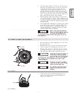
13. Insert two capscrews (2) in the holes lined up with the air inlet,
and alternately tighten them one turn at a time until the
assembly is snug.
14. Ensure the brake shaft (34) is positioned in the winch with the
shouldered end toward the brake. Install a new gasket, and
slide the brake assembly into place over the shaft.
15. Line the brake assembly up so that the dowel pin in the upright
engages the hole in the back of the support plate.
16. Install the remaining six capscrews (finger tight). Loosen the
two capscrews that hold the brake assembly together, and then
evenly tighten all eight capscrews. Using a crossing pattern,
torque the capscrews to 25 Nm (18 ft. lbs).
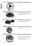
17. Reinstall the air fitting and air line, and refill the disc brake
with oil until the oil runs out of the oil level plug hole. Refer to
“LUBRICATION” section in the FA5A Winch Parts,
Operation and Maintenance Manual MHD56087 for suitable
oils. To avoid overfilling the disc brake, wait until oil stops
flowing out of the oil level hole before replacing the plug.
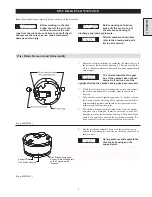
WARNING
After performing any maintenance
on the winch, test winch before
returning it to service.
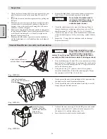
(Dwg. MHP1077)
Adjusting the Disc Brake
1.
No adjustments are required.
Testing the Disc Brake
1.
Ensure there is no load on the winch.
2.
Set the air pressure to 6.3 bar (90 psig) static (while the air
motor is not running).
3.
Disconnect the air line from the disc brake, and plug the air
line to prevent the loss of air pressure. (This will keep the disc
brake engaged while the winch is paying out.)
4.
Move the winch control valve handle or operate the pendant
control in the payout direction. The winch drum should not
turn. If it does turn, refer to the “TROUBLESHOOTING”
section.
Section 1
Capscrews
air line connection
Oil Drain Plug
Summary of Contents for FA5A
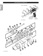
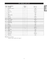
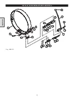
Page 10: ...10 DISC BRAKE PARTS DRAWING Dwg MHP0667 Dwg MHP0630 One Way Clutch Detail Section 1...
Page 19: ...19 Section 2 SERVICE NOTES...
Page 54: ...54 REDUCTION GEAR ASSEMBLY PARTS DRAWING Dwg MHP1221 Section 5...
Page 57: ...57 SERVICE NOTES...
Page 58: ...58 SERVICE NOTES...
Page 59: ...59 SERVICE NOTES...

