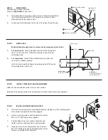
A.
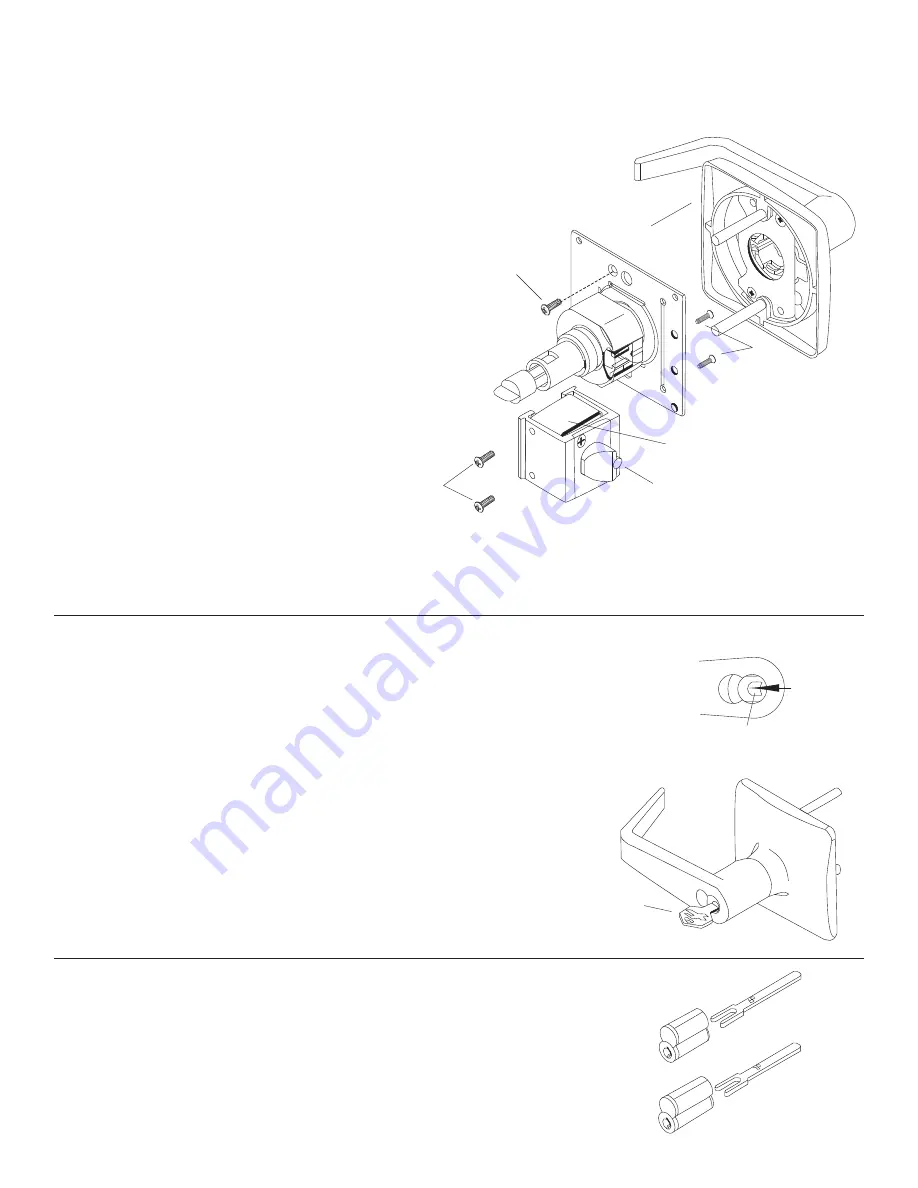
Temporarily, re-install latch assembly mounting screws (A) on the inside without
the inside mounting plate (this is to hold the support plates in place during
rehanding).
B.
Remove the outside trim retaining screw (B).
C.
Slide the outside trim (C) from the chassis assembly.
D.
Remove two (2) latch assembly mounting screws (D).
IMPORTANT: DO NOT remove or adjust hex nut.
E.
Slide the latch assembly from the chassis. Replace the latch
assembly mounting screws (D) finger tight.
F.
Reverse the latch assembly and remove the latch assembly
screws (A), then place it on the chassis. Make sure that chassis
housing engages the latch assembly. Retractor must also en-gage
the latch tail.
G.
Replace the two (2) latch assembly mounting screws
(A) making sure to align the tab of the latch assembly
with the slot of the mounting plate and screw holes of
the support plates.
H.
Slide the outside trim (C) onto the chassis.
I.
Replace the outside trim retaining screw (B).
J.
Remove latch assembly mounting screws (D).
Do not discard!
K.
See Step 4 to continue.
STEP 9
INSTRUCTIONS FOR REHANDING LOCK FOR DOOR BEVEL
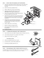
A.
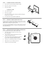
Insert control key into core and rotate 15 degrees clockwise. Pull key to remove core.
B.
Insert screwdriver into Figure “8” core hole and into lever retainer.
C.
Depress retainer and slide lever off spindle.
TO RE-INSTALL LEVER
D.
Slide lever over spindle and push on over retainer.
E.
Give a pull on lever to be sure retainer engaged lever.
F.
Re-install core with tailpiece pushed into core.
STEP 10
TO REMOVE INTERCHANGEABLE CORE CYLINDER LEVERS
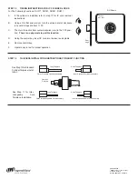
For proper function of the lock the right tailpiece must be used. Six pin cores should only
use the “6P” tailpiece and seven pin core should only use the “7P” tailpiece.
STEP 11
INTERCHANGEABLE CORE CYLINDER TAILPIECE INSTALLATION
Support plate
Latch assembly
Push
Retainer
Control Key
6 Pin Core
7 Pin Core
FA
LC
ON
FA
LC
ON
A
B
C
D

