22
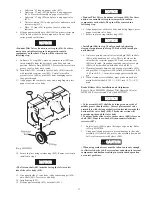
16. Screw two 1/2 - 13 UNC x 1-1/2 inch capscrews into the
threaded holes in the reducer housing (59). Turn both
screws evenly until housing is separated from drum. Attach
suitable lifting eyes to the capscrews and remove housing
from drum.
17. To further disassemble reduction gear refer to ‘Reduction
Gear Disassembly’ section.
Control Valve Disassembly
Lever Operated Control Valve
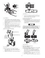
Refer to Dwg. MHP0654.
It is recommended that the valve be separated from the winch
and moved to a clean work area before disassembly of valve.
1.
If equipped with air actuated disc and/or drum band brakes,
disconnect the air line fittings at the shuttle valve body
(479).
2.
Disconnect the air inlet line at the valve inlet. On units
equipped with an emergency stop valve, disconnect air inlet
at the valve.
3.
To separate valve from motor, alternately loosen capscrews
(442) on adapter (440). Capscrews and washers (434)
cannot be removed until adapter is separated from valve
body (410). Separate valve as an assembly from winch
motor rotary valve housing (247).
4.
Remove capscrews (441) and separate adapter (440) from
valve body. Remove and discard gasket (424).
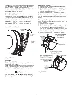
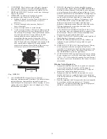
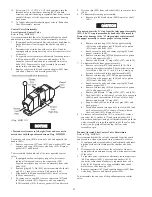
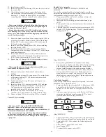
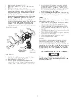
(Dwg. MHP1121)
NOTICE
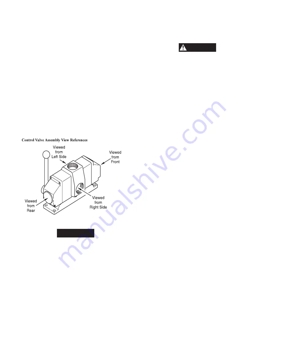
• Procedure references to left, right, front and rear are in
accordance with the positions shown on Dwg. MHP1121.
To remove valve cap (438) on control valve end opposite the
handle (449):
1.
Remove capscrews (437) and (439), and washers (433) and
separate valve cap (438) from valve body (410). Remove
gasket (411) and discard.
To disassemble the handle end of the lever operated control
valve:
1.
If equipped with an emergency stop valve, disconnect
tubing at fittings and remove four capscrews (528).
Separate emergency stop valve as an assembly from valve
body (410).
2.
Remove plug (447). Pin (445) has internal threads. Install
an 8-32 x 2 inch screw into pin. Pull out pin (445).
3.
Slide handle (449) and cross shaft (461) out of valve cap
(450) as an assembly.
4.
To remove valve cap (450), remove capscrews (437) and
(439) and washers (433). Separate valve cap assembly
(450) from body (410). Remove gasket (411) and discard.
5.
Drive out pin (409) from valve shaft (401) to remove clevis
(446).
6.
To disassemble rear poppet assembly:
a.
Remove pin (406) and shims (444) from valve shaft
(401).
CAUTION
• Do not separate the ‘O’ ring from the inlet poppet assembly
(423). The ‘O’ ring is permanently bonded to the assembly.
Removal or damage to the ‘O’ ring requires replacement of
the poppet assembly to ensure proper valve operation.
b.
Remove retainer ring (429). Pull poppet assembly
(423) along with poppet seat (428) and valve piston
(431) from valve body (410).
c.
Reach into valve body and remove spring (422) and
poppet restrictor (402).
d.
Remove retainer ring (432) and separate valve piston
(431) and poppet seat (428).
e.
Remove and discard ‘O’ rings (426), (427) and (430).
7.
To disassemble the front poppet assembly:
a.
Remove cotter pin (414) and washers (434). Note
quantity of washers installed. These washers are used
to establish a 0.06 to 0.12 inch (1.5 to 3.0 mm) gap
between washers and inlet poppet assembly (423).
b.
Remove retainer ring (429). Pull poppet assembly
(423) along with poppet seat (428) and valve piston
(431) from valve body (410).
c.
Reach into valve body and remove spring (422) and
exhaust poppet (420).
d.
Remove retainer ring (432) and separate valve piston
(431) and poppet seat (428).
e.
Remove and discard ‘O’ rings (426), (427) and (430).
f.
Push shaft (401) to the front of valve body to cause pin
(405) to push seat restrictor (403) out of valve body.
Remove and discard ‘O’ ring (404).
g.
Support shaft (401) on both sides of pins (405) and
push pins out.
h.
Insert allen wrench into open hole in sleeve (408) and
back out setscrew (407) a couple of turns to loosen
sleeve on shaft (401). Remove sleeve.
8.
To remove valve assemblies (413) or pins (412) remove
capscrew (465), washer (417) and spring washer (416).
From the exhaust port, using a soft material probe, push the
valve assembly or pin up through the top of the valve body
until it can be grasped from the top. Pull out valve
assembly or pin.
Pendant Operated Pilot Control Valve Disassembly
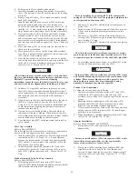
Refer to Dwg. MHP0653.
It is recommended that the valve be separated from the winch
and moved to a clean work area before disassembly of valve.
1.
If equipped with air actuated disc and/or drum band brakes,
disconnect the air line fittings at the shuttle valve body
(479).
2.
Disconnect the air inlet line at the valve inlet. On units
equipped with an emergency stop valve, disconnect air inlet
at the valve.
3.
To separate valve from motor, alternately loosen capscrews
(442) on adapter (440). Capscrews and washers (434)
cannot be removed until adapter is separated from valve
body (410). Separate valve as an assembly from winch
motor rotary valve housing (247).
4.
Remove capscrews (441) and separate adapter (440) from
valve body. Remove and discard gasket (424).
To disassemble the end caps of the pendant operated control
valve:
Summary of Contents for force5 FA5A-LAK1
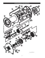
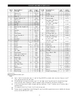
Page 34: ...34 WINCH ASSEMBLY PARTS DRAWING ...
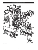
Page 36: ...36 MOTOR ASSEMBLY PARTS DRAWING ...
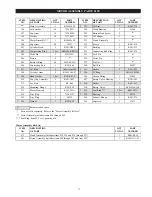
Page 38: ...38 DISC BRAKE ASSEMBLY PARTS DRAWING ...
Page 40: ...40 DRUM BAND BRAKE ASSEMBLY PARTS DRAWING ...
Page 42: ...42 LEVER OPERATED CONTROL VALVE ASSEMBLY PARTS DRAWING ...
Page 44: ...44 PENDANT OPERATED PILOT CONTROL VALVE ASSEMBLY PARTS DRAWING ...
Page 48: ...48 SHUTTLE VALVE ASSEMBLY PARTS DRAWING ...
Page 50: ...50 EMERGENCY STOP AND OVERLOAD ASSEMBLY PARTS DRAWING ...
Page 52: ...52 OPEN FRAME FACE WINCH ASSEMBLY PARTS DRAWING ...
Page 57: ...57 WINCH LABEL TAG LOCATION AND PART NUMBER REFERENCE DRAWING ...

