24
2.
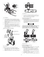
Disconnect air line from brake cylinder (121). With the aid
of a strap wrench, remove brake cylinder (121) and
components as an assembly by turning brake cylinder
counterclockwise until disconnected from brake bracket
(106).
3.
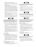
Disconnect brake bracket (106) from band assembly by
removing three capscrews (101), spacers (102) and spacer
tubes (103). Remove spacer plate (105).
4.
Disconnect brake bracket from motor end upright (68) by
removing two capscrews (107) and two capscrews (112).
DANGER
• Springs (124) and (127) exert a considerable force on cover
(125). Extreme care must be taken when disassembling the
cylinder assembly and removing cover (125).
5.
To disassemble the cylinder (121) assembly into its
component parts conduct the following:
a.
Use a press to compress the cover (125) enough to
remove retainer ring (126). Slowly, and carefully,
relax the load exerted on cover (125) by the springs
(124) and (127). Remove cover and springs.
b.
Remove washer (128).
c.
Remove piston (123) assembly.
d.
Disassemble piston assembly into component parts by
removing retainer ring (111) and separating cylinder
rod (108) from piston (123). Remove ‘O’ rings (123),
(109) and (110). Discard ‘O’ rings.
6.
Remove plunger (114) assembly and spring (113) from
brake bracket (106).
Manual Drum Band Brake:
1.
Remove capscrew (130) and washers (143). Remove the
brake handle (142).
2.
Remove capscrew (120) from cam plate (131).
3.
Remove bracket and components as an assembly by
removing capscrews (107 and 112).
4.
If required, separate assembly into component parts. Check
bearings allow smooth part movement, without sticking or
binding.
Free Spool Disassembly
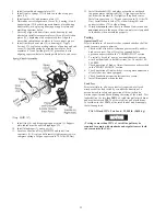
Refer to Dwg. MHP0927.
1.
Relieve pressure in the air lines and winch air components
by operating the winch control several times after the air
supply has been turned off.
WARNING
• Shut off, bleed down and disconnect the air supply line
before performing any disassembly procedures.
• Do not attempt repairs with load on wire rope.
2.
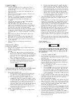
To assist in reassembly, place match marks on the housing
(503) and outboard upright (26).
3.
Remove free spool shifter assembly (506) by pulling it out
of housing (503). This assembly is held in place by ‘O’ ring
(404). Remove and discard ‘O’ ring (404).
4.
Plunger (508) and handle (509) are held in position by
Loctite
®
applied during assembly. To remove these parts,
carefully heat the shifter (507) until parts are removable.
5.
Remove capscrews (501) and washers (511). Remove cover
(2) and gasket (18). Discard gasket.
6.
Remove capscrews (502) and carefully pull housing (503)
away from outboard upright (26) while applying pressure
on shaft support (505) to keep it in winch drum (62).
7.
Remove shaft support (505) with output shaft (28) from
drum (62). Remove capscrews (504) and separate parts.
Reduction Gear
Refer to Dwg. MHP0649.
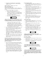
1.
Place the reduction gear assembly on a clean work bench
such that reducer housing (59) with oil seal (58) is down.
2.
Remove thrust washer (34) and output carrier assembly
(52).
3.
Remove the input carrier assembly (69) by grasping the
intermediate sun gear (45) and removing as an assembly.
This also removes the input sun gear (54). Ensure that
thrust bearing (56) and thrust washers (55), located on the
end of the input sun gear (54) are removed.
NOTICE
• Do not disassemble planetary assemblies further than
necessary to complete repairs. If planet gears (43) or (51) are
disassembled, note the position of all spacers, roller bearings
and shims to ensure correct reassembly.
4.
To disassemble an output planet gear (43) from the output
carrier (35) conduct the following:
a.
Before disassembly verify each gear (43) has a 0.005
to 0.032 inch (0.1 to 0.8 mm) end clearance.
b.
Using a small punch, drive roll pin (37) fully into
output planet pin (36).
c.
Gently tap and slowly remove output planet pin (36)
from output carrier (35). Using a punch, remove roll
pin (37) from planet pin and discard.
d.
Remove output planet gear (43) assembly. Take care to
prevent internal roller bearings (41) in each gear from
falling out during removal.
e.
Note the position and quantity of the washers (38),
(39) and (40) in each gear assembly. Keeping the
washers separated, by assembly, will assist in
reinstallation.
NOTICE
• If gear clearance is not within specification (0.005 to 0.032
inch [0.1 to 0.8 mm]) as determined in Step 4a., correct
location/quantity of washers (38), (39) and (40) must be
determined at assembly.
f.
Unless the roller bearings (41) or spacer (42) must be
replaced it is not recommended that these parts be
separated or removed from the output planet gear
assembly. Care must be taken to maintain the roller
bearing position. The output planet pin (36) can be
carefully reinserted into the gear to maintain bearing
position until reassembly.
g.
When planet gears are removed the thrust washer (44)
may be removed from the inside of the output carrier
(35).
5.
To disassemble an input planet gear (51) from the input
carrier (47) conduct the following:
a.
Before disassembly verify each gear (51) has a 0.005
to 0.032 inch (0.1 to 0.8 mm) end clearance.
b.
Using a small punch, drive roll pin (83) fully into
input planet pin (49).
c.
Gently tap and slowly remove input planet pin (49)
from input carrier (47). Using a punch, remove roll pin
(83) from planet pin and discard.
d.
Remove input planet gear (51) assembly. Take care to
prevent internal roller bearings (50) in each gear from
falling out during removal.
e.
Note the position and quantity of the washers (84),
(85) and (86) in each gear assembly. Keeping the
washers separated, by assembly, will assist in
reinstallation.
Summary of Contents for force5 FA5A-LAK1
Page 34: ...34 WINCH ASSEMBLY PARTS DRAWING ...
Page 36: ...36 MOTOR ASSEMBLY PARTS DRAWING ...
Page 38: ...38 DISC BRAKE ASSEMBLY PARTS DRAWING ...
Page 40: ...40 DRUM BAND BRAKE ASSEMBLY PARTS DRAWING ...
Page 42: ...42 LEVER OPERATED CONTROL VALVE ASSEMBLY PARTS DRAWING ...
Page 44: ...44 PENDANT OPERATED PILOT CONTROL VALVE ASSEMBLY PARTS DRAWING ...
Page 48: ...48 SHUTTLE VALVE ASSEMBLY PARTS DRAWING ...
Page 50: ...50 EMERGENCY STOP AND OVERLOAD ASSEMBLY PARTS DRAWING ...
Page 52: ...52 OPEN FRAME FACE WINCH ASSEMBLY PARTS DRAWING ...
Page 57: ...57 WINCH LABEL TAG LOCATION AND PART NUMBER REFERENCE DRAWING ...

