background image


Book 43212455 (11/03)   


15

SECTION 4 – SYSTEM DESCRIPTION 


General 

 
The CMH air compressors are semi-packaged, air cooled units designed for power take-off applications.  
Each unit is designed to operate at ambient temperatures from - 10

°

F to 125

°

F (-23.3

°

C to 51.7

°

C).  For 

the actual delivery of each unit at its rated operating pressure, refer to the typical General Data Decal 
supplied with each unit, and to the table in Section 5. 
 
The unit includes an oil flooded, rotary, screw-type air compressor, a compressor inlet system, a capacity 
control system, a compressor lubricating oil system, a compressor discharge system as well as basic 
instrumentation.  The compressor inlet system includes an air intake cleaner with a service indicator.  The 
capacity control system includes a pressure regulator linked to a compressor inlet unloader valve.  The 
compressor lubricating oil system includes an air-cooled type oil cooler, an oil filter, and oil control valve 
and an oil separator tank and air receiver.  The oil cooler is of the fin and tube-type construction that 
requires forced draft cooling air.  Basic instrumentation includes compressor discharge air pressure and 
temperature gauges, and air cleaner restriction indicator. 
 
The enclosure cabinet, in which most of the components are mounted, is of heavy gauge sheet steel and 
is equipped with easy opening access panels for performing routine maintenance functions.  Most routine 
service can be performed without removing any panels. 
 
Compression in the screw-type air compressor is created by the meshing of two sets of helical rotors 
(male and female) on parallel shafts enclosed in a heavy-duty cast iron housing with air inlet and outlet 
ports located at opposite ends.  The male rotor has four lobes, 90 degrees apart and the female rotor has 
six grooves 60 degrees apart.  The grooves of the female rotor mesh with and are driven by the male 
rotor.  Thrust taper roller bearings at the rear of the air end prevent longitudinal movement of the rotors.  
As rotation of the compressor occurs, the rotors unmesh and free air is drawn into the cavities or pockets 
between the male rotor lobes and the grooves of the female rotor.  The air is trapped in these pockets and 
follows the direction of rotation of each rotor.  As soon as the inlet port is closed, the compression cycle 
begins and the trapped air is directed to the opposite or discharge side of the rotor housing.  As the rotors 
mesh, the normal free volume of air is decreased and the pressure increased until the closing pocket 
reaches the discharge port.  Cooled lubricating oil is admitted to the compressor by being injected, in 
metered amounts, directly into the rotor housing so that it passes on with the air being compressed.  This 
removes the heat of compression to a large degree and results in a relatively low, final discharge air 
temperature. 
 
Since the CMH Series compressor is of the positive displacement type, an air flow control system must be 
provided to regulate the volume of air passing through the compressor to match the amount of service air 
required by the customer. 
 
Constant speed control unloads the compressor at a predetermined pressure while the driving unit 
continues to operate at full speed.  This is accomplished by an air operated regulator closing off the intake 
to the compressor in an infinitely variable or stepless manner through the inlet unloader valve. 
 
The discharge air pressure can be controlled between 77 and 200 psig (531 to 1379 kPa) by simple 
readjustment of the speed and pressure regulator adjusting screw. 
 

Summary of Contents for HP600CMH

Page 1: ...manual This manual must be available to the personnel who operate and maintain this machine Doosan purchased Bobcat Company from Ingersoll Rand Company in 2007 Any reference to Ingersoll Rand Company or use of trademarks service marks logos or other proprietary identifying marks belonging to Ingersoll Rand Company in this manual is historical or nominative in nature and is not meant to suggest a c...

Page 2: ...Book 43212455 11 03 2 Quality Policy We will supply products and services that consistently meet the requirements of our customers and each other ...

Page 3: ...Y SECTION 2 WARRANTY SECTION 3 WARRANTY REGISTRATION SECTION 4 SYSTEM DESCRIPTION SECTION 5 INSTALLATION SECTION 6 OPERATION SECTION 7 GENERAL DATA SECTION 8 MAINTENANCE LUBRICATION SECTION 9 PARTS ORDERING SECTION 10 PARTS LIST SECTION 11 COMMON FASTENERS ...

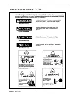
Page 4: ...safety related parts such as coupling hitch drawbar components road wheels and lifting bail should be checked for total security All components which are loose damaged or unserviceable must be rectified without delay Air discharged from this machine may contain carbon monoxide or other contaminants which will cause serious injury or death Do not breathe this air This machine produces loud noise wi...

Page 5: ... vent valve before performing any service The discharged air contains a very small percentage of compressor lubricating oil and care should be taken to ensure that downstream equipment is compatible If the discharged air is to be ultimately released into a confined space adequate ventilation must be provided When using compressed air always use appropriate personal protective equipment All pressur...

Page 6: ... data sheets for compressor and engine lubricants should be obtained from the lubricant supplier Do NOT start or operate this machine in a confined area Avoid breathing exhaust fumes when working on or near the machine This machine may include such materials as oil diesel fuel antifreeze brake fluid oil air filters and batteries which may require proper disposal when performing maintenance and ser...

Page 7: ...ic requirements Break away cables safety chains are connected to the towing vehicle The machine must be towed in a level attitude in order to maintain correct handling braking and lighting functions This can be achieved by correct selection and adjustment of the vehicle towing hitch and on variable height running gear adjustment of the drawbar 1 Make sure wheels tires and tow bar connectors are in...

Page 8: ...Book 43212455 11 03 8 IMPORTANT SAFETY INSTRUCTIONS ...

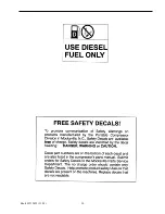
Page 9: ...Book 43212455 11 03 9 ...

Page 10: ...Book 43212455 11 03 10 ...

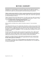
Page 11: ...a maintenance agreement Formal enrollment is required Ingersoll Rand will provide a new part or repaired part at its election in place of any part which is found upon its inspection to be defective in material and workmanship during the period prescribed above Such part will be repaired or replaced without charge to the initial user during normal working hours at the place of business of an Ingers...

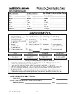
Page 12: ...d States require notification be made to initiate the machine warranty Fill out the Warranty Registration Form in this section keep a copy for your records and mail form to Ingersoll Rand Company Portable Compressor Division P O Box 668 Mocksville North Carolina 27028 Attn Warranty Department Note Completion of this form validates the warranty Engine Registration No engine registration required Mu...

Page 13: ...odel Unit S N Engine S N Date Delivered Unit Hours Airend S N Truck S N Truck Engine S N SERVICING DISTRIBUTOR USER ACKNOWLEDGMENT 1 The Purchaser has been instructed and or has read the manual and understands proper preventative maintenance general operation and safety precautions 2 The warranty and limitation of liability has been reviewed and understood by the owner user 3 In the event that thi...

Page 14: ...Book 43212455 11 03 14 fold ...

Page 15: ...utlet ports located at opposite ends The male rotor has four lobes 90 degrees apart and the female rotor has six grooves 60 degrees apart The grooves of the female rotor mesh with and are driven by the male rotor Thrust taper roller bearings at the rear of the air end prevent longitudinal movement of the rotors As rotation of the compressor occurs the rotors unmesh and free air is drawn into the c...

Page 16: ... the receiver separator choose a location that is on the same level as or lower than the compressor package Ample space must be provided around the receiver to ensure the proper installation of all piping connections In addition the receiver separator must be located so that the separator element may be removed for inspection and service Refer to the appropriate separator foundation plan A condens...

Page 17: ...Parker Hannifin 213 or Aeroquip FC350 or equivalent Compressor Module to Oil Cooler Drain 6 JIC Parker Hannifin 213 or Aeroquip FC350 or equivalent Oil Cooler to Oil Temp Bypass Valve Port B 24 JIC Parker Hannifin 206 or Aeroquip FC300 or equivalent Oil Cooler to Oil Temp Bypass Valve Port C 24 JIC Parker Hannifin 206 or Aeroquip FC300 or equivalent Airend Discharge to Receiver Separator Inlet 32 ...

Page 18: ... A normally closed type thermal switch factory set at 248 F 120 C is supplied as standard equipment on these units This switch is supplied for 12 24 volt DC As an option this switch may be supplied for 125 volt AC A thermal sensor switch also set at 248 F 120 C normally closed is provided as extra protection in the receiver separator It is to be wired in series with the airend temperature switch b...

Page 19: ...sal There are many types of universal joints that can be used However a constant velocity universal joint as previously described will reduce the possibility of torsional vibration If a slip joint or spline is used on the drive system it should be placed between the two universal joints for best results Regulation The standard regulation system supplied with CMH Series Compressors is designed to p...

Page 20: ...manifold tubing HR2 5 Remove cap on manifold tube between pump and filter and inject 7 gallons 26L into the manifold tubing BEFORE STARTING Do not connect the air discharge on this unit into a common header with any other unit of any description or any other source of compressed air without first making sure a check valve is used between the header and the unit If this unit is connected in paralle...

Page 21: ...Book 43212455 11 03 21 This will maximize the life of the compressor Be sure no one is IN or ON the compressor unit ...

Page 22: ...ow the unit to sit stopped with pressure in the receiver separator system As a precaution after the automatic blow down period 2 minutes open the manual blow down valve EQUIPMENT PROTECTION NOTE Do NOT wire around or bypass a shutdown sensor or switch This unit is protected by two 2 shutdown switches at the following locations High Discharge Air Temperature 1 At the airend outlet 2 In the safety v...

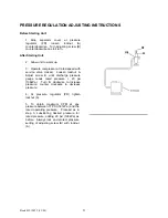
Page 23: ...rvice valve closed Loosen locknut A Adjust screw B until discharge pressure gauge reads rated pressure 20 psi 138kPa Turn B clockwise to increase pressure counter clockwise to decrease pressure 4 At pressure regulator PR tighten locknut A 5 To obtain maximum CFM at any pressure between 77 PSI 531kPa and the rated operating pressure Proceed as in step 3 substituting desired pressure for rated press...

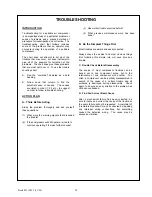
Page 24: ...g signals that preceded the trouble 3 Has similar trouble occurred before 4 What previous maintenance work has been done B Do the Simplest Things First Most troubles are simple and easily corrected Always check the easiest and most obvious things first following this simple rule will save time and trouble C Double Check Before Disassembly The source of most compressor troubles can be traced not to...

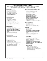
Page 25: ...Pressure Regulator Malfunctioning Inlet Unloader Butterfly Valve Defective Separator Element Ice in Regulation Lines Orifice Excessive Compressor Oil Temperature Ambient Temperature Too High Out of Level 15 degrees Low Oil Level Dirty Cooler Dirty Operating Conditions Operating Pressure Too High Malfunctioning Thermostat Defective Minimum Pressure Valve Blocked or Restricted Oil Lines Airend Malfu...

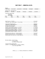
Page 26: ... Safety 35377696 Overall Length Compressor Module inch mm 51 0 1295 Overall Height Compressor Module inch mm 42 0 1067 Overall Width Compressor Module inch mm 40 3 1024 Overall Length Air Receiver Module inch mm 25 0 635 Overall Height Air Receiver Module inch mm 88 6 1234 Overall Width Air Receiver Module inch mm 22 5 572 Weight Compressor Module pounds kilograms 1540 699 Weight Air Receiver Modu...

Page 27: ... operated The optimum operating level is midway of the sight tube on the side of the receiver tank See the decal beside the sight tube If the oil level is not in the OK range make appropriate corrections Add or Drain A totally filled sight tube in which the level is not visible indicates an over full condition and requires that oil be drained AIR CLEANER This unit is equipped with AIR FILTER RESTR...

Page 28: ...osits and a new element is not available cleaning can be accomplished by washing using the air cleaner element manufacturer s recommendations NOTE It is recommended that replacement elements be installed in the unit The elements just removed for cleaning can be washed and stored as future replacement elements In addition the air cleaner system housing and piping should be inspected every month for...

Page 29: ...that cooling efficiency is impaired a resulting high discharge air temperature is likely to occur causing shut down of the unit To correct this situation it will be necessary to clean the coolers using a cleaning compound in accordance with the manufacturer s recommendations HOSES Each month it is recommended that all of the intake lines to and from the air cleaners and flexible hoses used for air...

Page 30: ...llows High pressure air can cause severe injury or death from hot oil and flying parts Always relieve pressure before removing caps plugs covers or other parts from pressurized air system Open the service air valve s to ensure that system is relieved of all pressure Close the valve s Turn the spin on filter element counterclockwise to remove it from the filter housing Inspect the filter NOTICE If ...

Page 31: ...m of separator tank When adding oil remove and replace make tight plug on side of separator tank In the compressor lubricating and cooling system separation of the oil from the compressed air takes place in the receiver separator tank As the compressed air enters the tank the change in velocity and direction drop out most of the oil from the air Additional separation takes place in the oil separat...

Page 32: ...rom the element gasket connection Place a straightedge across top of element and measure from bottom of straightedge to bottom of element See drawing below Replace scavenge tube in cover cover is still off of tank Measure from bottom of cover to end of scavenge tube Measurement should be from 1 8 to less than the element measurement If not cut to size Remove scavenge tube Reposition cover use care...

Page 33: ...earlier in this section 2 Thoroughly clean scavenge line any orifice and check valve 3 Assure minimum pressure valve if so equipped has proper setting 4 Run unit at rated operating pressure for 30 to 40 minutes to permit element to clear itself EXTERIOR FINISH CARE The unit was painted and heat cured at the factory with a high quality thermostat polyester powder coating The following care will ens...

Page 34: ...t Primer to all bare metal areas and allow to dry 8 Apply 2 medium wet coats of Dupont 222S Adhesion Promoter over the entire area to be painted with a 5 minute flash in between coats 9 To apply the texture coat use Dupont 1854S Tuffcoat Primer The proper technique to do this is to spray the Tuffcoat Primer using a pressure pot and use about 2 5 pounds of air pressure This will allow the primer to...

Page 35: ...aner Precleaner Dumps C Hoses Oil Air Intake Hydraulic C Automatic Shutdown System Test C Air Cleaner System Visual C Compressor Oil Cooler Exterior C Clean Fasteners C Air Cleaner Elements WI Compressor Oil Filter Element R Compressor Oil R Shutdown Switch Settings Test C Scavenger Orifice Related Parts Clean Oil Separator Element R Disregard if not appropriate for this particular machine Unit Da...

Page 36: ... Lubricating and Cooling Oil System Relatively cool lubricating oil is admitted under pressure to the compressor bearings and is also injected in metered amounts directly to the rotor chamber All of the oil thus introduced mixes with and passes on with the air being compressed thus removing the heat of compression to a large degree On its way to the final discharge connection the air passes throug...

Page 37: ...Book 43212455 11 03 37 ...

Page 38: ...time most of the sediment will be in suspension and will drain more readily Shorter oil change intervals may be necessary if unit is operated under adverse conditions Do not under any circumstances open any drain cocks remove any plugs or the oil filler plug from the compressor lubricating and cooling oil system without making sure the air receiver system had been completely relieved of all air pr...

Page 39: ...trated parts breakdown illustrates and lists the various assemblies subassemblies and detailed parts which make up this particular machine This covers the standard models and the more popular options that are available A series of illustrations show each part distinctly and in location relative to the other parts in the assembly The part number the description of the part and the quantity of parts...

Page 40: ... attached to the unit c Always specify the number of the parts list publication d Always specify the quantity of parts required e Always specify the part number as well as the description of the part or parts exactly as it is given on the parts list illustration In the event parts are being returned to your nearest sales office autonomous company or authorized distributor for inspection or repair ...

Page 41: ... respect to this order whether based on contract warranty negligence indemnity strict liability or otherwise shall not exceed the purchase price of the part upon which such liability is based The Company shall in no event be liable to the Purchaser any successors in interest or any beneficiary of this order for any consequential incidental indirect special or punitive damages arising out of this o...

Page 42: ... airend rebuild kits Airend Pricing and Procedure All new and remanufactured airends will have 30 discount of list price 0 7multiplier if a used airend is to be returned for exchange If no airend is to be returned then the discount is 10 of list 0 9 multiplier Call Ingersoll Rand Customer Service for assistance when replacing competitive non IR airend with an Ingersoll Rand remanufactured or new a...

Page 43: ...in the system separately i e valves switches manifolds piping and or hose oil cooler and separator tank If necessary remove component flush and replace if either inner or outer covering is visibly damaged D Check condition of all compressor airend oil hoses and replace if either inner or outer covering is visible damaged E Remove separator cover and inspect separator element If element shows any s...

Page 44: ......
Reviews: