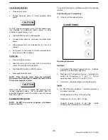
STARTING/OPERATING
•
Close service valve.
•
Engage hydraulic pump at lowest possible driver
speed
Do NOT engage compressor motor at driver speed above
idle. Damage to compressor motor, pump, or other
driveline component scan occur.
•
Flip RUN/STOP switch to RUN position.
•
Increase driver speed to compressor operation rated
speed.
•
Allow compressor to run unloaded five (5) to ten (10)
minutes.
•
Compressor is now ready to furnish compressed air
when service valve is opened.
STOPPING
•
Close air service valve(s).
•
Allow the unit to run at “no load” for 3 to 5 minutes to
reduce the compressor temperature.
•
Flip RUN/STOP switch to STOP position.
•
Disengage hydraulic pump.
NOTE: Once the drive motor stops, the automatic
blow-down valve will begin to relieve all pressure from
the receiver separator system.
Never allow the unit to sit stopped with pressure in the
receiver separator system. As a precaution, after the
automatic blowdown period (3 minutes), open the manual
blow-down valve.
EQUIPMENT PROTECTION
NOTE: Do NOT wire around or bypass a shutdown
sensor or switch.
This unit is protected by a shutdown switch at the following
location:
High Discharge Air Temperature
(1) In the end of the separator tank.
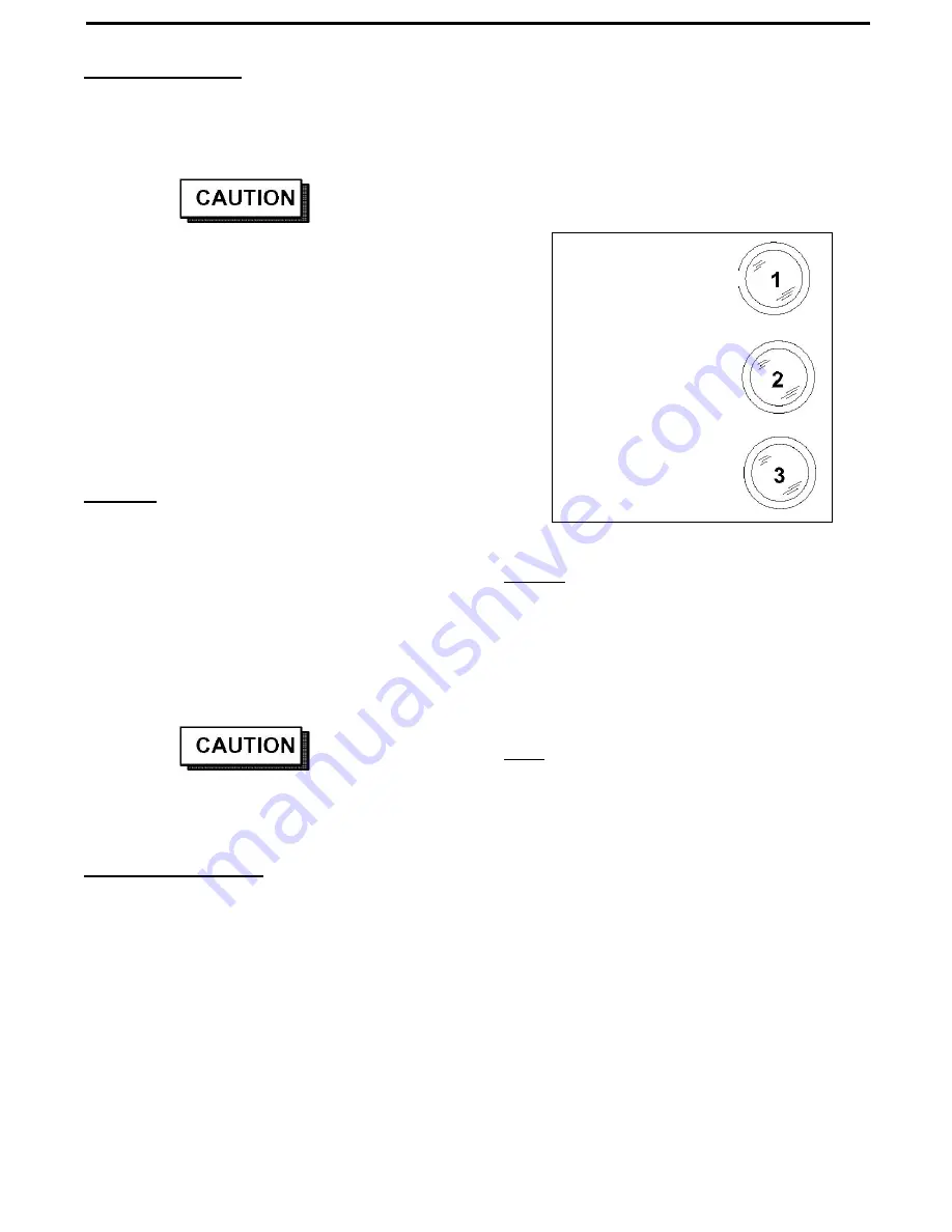
GAUGE PANEL
Operating Instruments
On Panel
1. Compressor Discharge Pressure Gauge – Indicates
pressure in receiver tank, psig (kPa).
2. Discharge Air Temperature Gauge – Indicates dis-
charge air temperature in °F and °C. Normal
operating range: 185°F/85°C to 248°F/120°C.
3. Hour meter – Indicates elapsed unit operating time.
Inside
4. Air Filter Restriction Indicator – Indicates compressor
air cleaner restriction.
Normal operation (<20-in. H2O), green flag.
Needs service, (>20-in. H2O), red flag.
(Indicator located at base of inlet filter. Visible
through grille at discharge end of machine).
(
25
)
Manual P/N 22189203 (01/17/2005)
Summary of Contents for HP60CMH
Page 6: ... 6 Manual P N 22189203 01 17 2005 ...
Page 7: ... 7 Manual P N 22189203 01 17 2005 ...
Page 8: ... 8 Manual P N 22189203 01 17 2005 ...
Page 9: ... 9 Manual P N 22189203 01 17 2005 9 Manual P N 22189203 01 17 2005 ...
Page 10: ... 10 Manual P N 22189203 01 17 2005 10 Manual P N 22189203 01 17 2005 ...
Page 41: ... 41 Manual P N 22189203 01 17 2005 ...
Page 43: ... 43 Manual P N 22189203 01 17 2005 ...
Page 44: ...22173538 44 Manual P N 22189203 01 17 2005 ...
Page 45: ...UNLOADER ASSEMBLY 45 Manual P N 22189203 01 17 2005 ...
Page 46: ...Separator Tank 46 Manual P N 22189203 01 17 2005 ...
Page 47: ... 47 Manual P N 22189203 01 17 2005 ...
Page 48: ... 48 Manual P N 22189203 01 17 2005 ...
Page 49: ...AIR OIL HYDRAULIC PIPING 49 Manual P N 22189203 01 17 2005 ...
Page 50: ...AIR OIL HYDRAULIC PIPING 50 Manual P N 22189203 01 17 2005 ...
Page 52: ... 52 Manual P N 22189203 01 17 2005 Wiring Diagram ...

