background image


(

52

Manual P/N 22189203 (01/17/2005)


Wiring Diagram 


Summary of Contents for HP60CMH

Page 1: ...hased Bobcat Company from Ingersoll Rand Company in 2007 Any reference to Ingersoll Rand Company or use of trademarks service marks logos or other proprietary identifying marks belonging to Ingersoll Rand Company in this manual is historical or nominative in nature and is not meant to suggest a current affiliation between Ingersoll Rand Company and Doosan Company or the products of either ...

Page 2: ...QUALITY POLICY We will supply products and services that consistently meet the requirements of our customers and each other 2 Manual P N 22189203 01 17 2005 ...

Page 3: ...ION 2 WARRANTY REGISTRATION SECTION 3 INSALLATION SECTION 4 GENERAL DATA SECTION 5 OPERATION SECTION 6 MAINTENANCE SECTION 7 LUBRICATION SECTION 8 TROUBLESHOOTING SECTION 9 PARTS ODERING SECTION 10 PARTS LIST 3 Manual P N 22189203 01 17 2005 ...

Page 4: ... is compatible If the discharged air is to be ultimately released into a confined space adequate ventilation must be provided When using compressed air always use appropriate personal protective equipment All pressure containing parts especially flexible hoses and their couplings must be regularly inspected be free from defects and be replaced according to the Manual instructions Avoid bodily cont...

Page 5: ...fan blade can cause serious injury Do not operate without guard in place Use care to avoid contacting hot surfaces engine exhaust manifold and piping air receiver and air discharge piping etc Ether is an extremely volatile highly flammable gas USE SPARINGLY If too much is injected it may result in costly damage to the engine Never allow the unit to sit stopped with pressure in the receiver separat...

Page 6: ... 6 Manual P N 22189203 01 17 2005 ...

Page 7: ... 7 Manual P N 22189203 01 17 2005 ...

Page 8: ... 8 Manual P N 22189203 01 17 2005 ...

Page 9: ... 9 Manual P N 22189203 01 17 2005 9 Manual P N 22189203 01 17 2005 ...

Page 10: ... 10 Manual P N 22189203 01 17 2005 10 Manual P N 22189203 01 17 2005 ...

Page 11: ...afety decals DANGER WARNING or CAUTION Decal part numbers are on the bottom of each decal and are also listed in the compressor s parts manual Submit orders for Safety Decals to the Mocksville Parts Service Department The no charge order should contain only Safety Decals Help promote product safety Assure that decals are present on the machines Replace decals that are not readable 11 Manual P N 22...

Page 12: ...from shipment to or the accumulation of 4 000 hours of service by the initial user For Air Ends the warranty against defects will include replacement of the complete Air End provided the original Air End is returned assembled and unopened C 1 Portable Compressor Airend Limited Optional Warranty The earlier of sixty 60 months from shipment to or the accumulation of 10 000 hours of service The optio...

Page 13: ...iod prescribed above Such part will be repaired or replaced without charge to the initial user during normal working hours at the place of business of an Ingersoll Rand distributor authorized to sell the type of equipment involved or other establishment authorized by Ingersoll Rand User must present proof of purchase at the time of exercising warranty The above warrantees do not apply to failures ...

Page 14: ...5 yrs 5000 hours using OEM fluids filters with 250 deductible 2 yrs 4000 hours using IR fluids filters IN GENERATORS AS OF 1 1 01 24 2000 Deutz 24 2000 Available at dealer Ingersoll Rand 24 4000 5 years 10 000 hours when using genuine Ingersoll Rand fluids and parts Refer to operator s manual Kubota North America Only 24 2000 Major components 36 months 3000 hrs parts only Western Europe Oceania 24...

Page 15: ...lation of 10 000 hours of service The optional warranty is limited to defects in major components rotors housings gears bearings and is automatically available when the following three conditions are met 1 The original airend is returned assembled and unopened 2 Submissions of proof that Ingersoll Rand fluid filters and separators have been used Refer to the Operation and Parts manual for the corr...

Page 16: ...ines shipped outside the United States require notification be made to initiate the machine warranty Fill out the Warranty Registration Form in this section keep a copy for your records and mail form to Ingersoll Rand Company Portable Compressor Division P O Box 868 Mocksville North Carolina 27028 Attn Warranty Department Note Completion of this form validates the warranty 16 Manual P N 22189203 0...

Page 17: ...__________ Model Unit S N Engine S N Date Delivered Unit Hours Airend S N Truck S N Truck Engine S N SERVICING DISTRIBUTOR USER ACKNOWLEDGEMENT 1 The Purchaser has been instructed and or has read the manual and understands proper preventative maintenance general operation and safety precautions 2 The warranty and limitation of liability has been reviewed and understood by the owner user 3 In the e...

Page 18: ... 18 Manual P N 22189203 01 17 2005 Ingersoll Rand Company Portable Compressor Division P O Box 868 Mocksville North Carolina 27028 Attention Warranty Department fold ...

Page 19: ...inal discharge air temperature Since the Ingersoll Rand Compressor Module Series unit is of the positive displacement type an airflow control system must be provided to regulate the volume of air passing through the compressor to match the amount of service air required by the customer Constant speed control unloads the compressor at a predetermined pressure while the driving unit continues to ope...

Page 20: ...ing Each unit is supplied with an air cleaner to protect the compressor from normal airborne dust and dirt If necessary the air cleaner may be removed and remotely mounted for ease in accessibility PIPING General Ingersoll Rand Compressor Module units will require customer provided piping from the compressor module to the hydraulic supply and the air service piping These hoses are not provided wit...

Page 21: ...NOT practical to operate this unit without a hydraulic cooler With a typical 40 gallon tank depending on beginning hydraulic oil temperature testing dem onstrates that the unit is limited to 20 minutes of full load operation in an eight hour period Tanks cool very slowly 12 hours are generally needed for the oil to cool to within 30 F of the surrounding air temperature At full load with a typical ...

Page 22: ...ted and tank should be baffled It is desirable that an outlet strainer be fitted A cut off valve for service should be included along with a clean out port Tank must be vented to atmosphere and should include adequate expansion volume Hydraulic Filtration In addition to a tank strainer a hydraulic filter must be fitted either in the return line or in the pressure line We highly recommend pressure ...

Page 23: ...nts 12VDC Fan 8 5 Amps 18 Amps Compressor Lube Capacity Refill U S gal liters 2 7 6 2 7 6 Unit Measurements Weights Overall Length inch mm 28 5 724 28 5 724 Overall Height inch mm 22 1 562 22 1 562 Overall Width inch mm 20 6 524 20 6 524 Weight Compressor Module pounds kilograms 328 149 328 149 Weight system with lubricants pounds kilograms 342 155 342 155 Service Parts Compressor Oil Filter Eleme...

Page 24: ...rations personnel Unrestricted airflow from a hose will result in a whip ping motion of the hose which can cause serious injury or death A safety device must be attached to the hose at the source of supply to reduce pressure in case of hose failure or other sudden pressure release Reference OSHA regulation 29 CFR Section 1926 302 b Open manual blowdown valve to ensure pressure is relieved in recei...

Page 25: ...allow the unit to sit stopped with pressure in the receiver separator system As a precaution after the automatic blowdown period 3 minutes open the manual blow down valve EQUIPMENT PROTECTION NOTE Do NOT wire around or bypass a shutdown sensor or switch This unit is protected by a shutdown switch at the following location High Discharge Air Temperature 1 In the end of the separator tank GAUGE PANE...

Page 26: ...Allow unit to warm up at least five minutes and then if equipped place the Start Run Valve Switch in the AIR position to obtain full service air pressure 4 With Service Air Valve closed turn the adjusting screw C clockwise until the discharge pressure reaches 185 psi range 10psi Tighten jam nut D 5 Replace regulator valve cover A if equipped 6 To select any pressure range fro 80 to150 psi change a...

Page 27: ...s running AIRCLEANER This unit is equipped with an AIR FILTER RESTRICTION INDICATOR on the clean air side of the compressor air inlet This should be checked daily during operation If the indicator shows red with the unit operating at full speed servicing of the cleaner element is necessary If flagged the air filter restriction indicator must be reset after unit is shutdown and the air cleaners are...

Page 28: ...f grease oil and dirt from the exterior surfaces of the oil cooler core so that the entire cooling area can transmit the heat of the lubricating and cooling oil to the air stream In the event foreign deposits such as sludge and lacquer accumulate in the oil cooler to the extent that its cooling efficiency is impaired a resulting high discharge air temperature is likely to occur causing shut down o...

Page 29: ...ubricating oil has improper characteristics and should be immediately changed 3 Inspect the oil filter head to be sure the gasket was removed with the oil filter element Clean the gasket seal area on the oil filter head NOTICE Installing a new oil filter element when the old gasket remains on the filter head will cause an oil leak and can cause property damage 4 Lubricate the new filter gasket wit...

Page 30: ...unit by rotating counterclockwise NOTE If there is any indication of formation of varnishes shellacs or lacquers on the oil filter element it is a warning the compressor lubricating oil has improper characteristics and should be im mediately changed 3 Inspect the separator head to be sure the gasket was removed with the oil filter element Clean the gasket seal area on the head NOTE Installing a ne...

Page 31: ...ect battery cables and open manual blowdown valve Never operate this machine with any guards removed Use extreme care to avoid contacting hot surfaces air receiver and air discharge piping etc Inch and metric hardware was used in the design and assembly of this unit Consult parts manual for clar ification of usage 31 Manual P N 22189203 01 17 2005 ...

Page 32: ... Test C Air Cleaner System Visual C Compressor Oil Cooler Exterior C CLEAN Fasteners C Air Cleaner Elements WI Compressor Oil Filter Element R Compressor Oil R Shutdown Switch Settings Test C Scavenger Orifice Related Parts CLEAN Oil Separator Element R Disregard if not appropriate for this particular machine R replace C check adjust if necessary WI OR when indicated L Lubricate 32 Manual P N 2218...

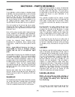
Page 33: ...elatively cool lubricating oil is admitted under pressure to the compressor bearings and is also injected in metered amounts directly to the rotor chamber All of the oil thus introduced mixes with and passes on with the air being compressed thus removing the heat of compression to a large degree On its way to the final discharge connection the air passes through a receiver separator A scavenger li...

Page 34: ...e sediment will be in suspension and will drain more readily Shorter oil change intervals may be necessary if unit is operated under adverse conditions Do not under any circumstances open any drain cocks remove any plugs or the oil filler plug from the compressor lubricating and cooling oil system without making sure the air receiver system has been completely relieved of all air pressure Some oil...

Page 35: ...tor s manual warranty section for details or contact your Ingersoll Rand representative Recommended Fluid 1 Gal 3 8 Liter 5 Gal 19 0 Liter 55 Gal 208 2 Liter IR Pro Tect 36899698 36899706 36899714 IR XHP 505 35382928 35365188 35365170 IR Performance 500 35382936 35382944 IR XHP1001 35612738 35300516 35 Manual P N 22189203 01 17 2005 ...

Page 36: ...ate is it safe to continue operating it to make further checks B Do The Simplest Things First Most troubles are simple and easily corrected For example most complaints are low capacity which may be caused by too low an engine speed or compressor over heats which may be caused by low oil level Always check the easiest and most obvious things first following this simple rule will save time and troub...

Page 37: ... in Regulation Lines Orifice Fan s Will Not Run Clogged With Ice Snow Debris Defective Pressure Switch Defective Relay6 Defective Wiring Blown Fuse Defective Fan Motor greater than less than Excessive Compressor Oil Temperature Ambient Temperature Too High Out of Level 15 degrees Low Oil Level Wrong Lube Oil Dirty Cooler Dirty Operating Conditions Clogged Oil Filter Elements Malfunctioning Fan Def...

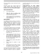
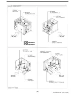
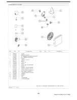
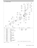
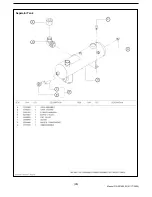
Page 38: ... models and the more popular options that are available A series of illustrations show each part distinctly and in location relative to the other parts in the assembly The part number the description of the part and the quantity of parts required are shown on each illustration or on adjacent page The quantities specified are the number of parts used per one assembly and are not necessarily the tot...

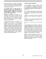
Page 39: ...er form is used for acceptance of an offer it is expressly understood and agreed that the terms and conditions of such order form shall not apply unless expressly agreed to by Ingersoll Rand Company Company in writing No additional or contrary terms will be binding upon the Company unless expressly agreed to in writing Taxes Any tax or other governmental charge now or hereafter levied upon the pro...

Page 40: ... or not such loss or damage is based on contract warranty negligence indemnity strict liability or otherwise AIREND EXCHANGE PROGRAM Your Ingersoll Rand Company Onboard Power Solutions Offices and authorized distributors as well as Ingersoll Rand International autonomous companies and authorized distributors now have an airend exchange program to benefit portable com pressor users On the airend ex...

Page 41: ... 41 Manual P N 22189203 01 17 2005 ...

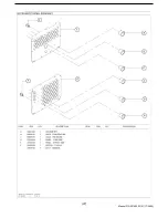
Page 42: ...22147409 90CFM Cooler Assembly 22489389 60CFM Cooler Assembly 42 Manual P N 22189203 01 17 2005 ...

Page 43: ... 43 Manual P N 22189203 01 17 2005 ...

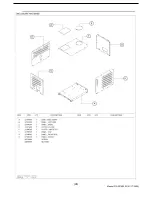
Page 44: ...22173538 44 Manual P N 22189203 01 17 2005 ...

Page 45: ...UNLOADER ASSEMBLY 45 Manual P N 22189203 01 17 2005 ...

Page 46: ...Separator Tank 46 Manual P N 22189203 01 17 2005 ...

Page 47: ... 47 Manual P N 22189203 01 17 2005 ...

Page 48: ... 48 Manual P N 22189203 01 17 2005 ...

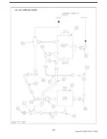
Page 49: ...AIR OIL HYDRAULIC PIPING 49 Manual P N 22189203 01 17 2005 ...

Page 50: ...AIR OIL HYDRAULIC PIPING 50 Manual P N 22189203 01 17 2005 ...

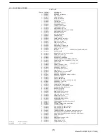
Page 51: ... 22180889 HOSE ASSY 12X22 JIC 40 35576115 3 4 SERVICE BALL VALVE 41 95992848 ELBOW 90 DEG 42 22179436 CONN SWIVEL 16JIC X 1 0 FNPT 43 95944617 BSHG RDCNPT100X075 44 36757581 DISCHARGE PRESSURE SWITCH 12 PSIG 45 36882975 HOSE ASSY 12X10 46 35379932 PL HEX 1 2 20UNF 47 35369354 ELB ML 1 4NPTX3 8TB 48 95954913 REDUCER 1 5 8 SAE X 1 5 16 FEMALE SAE 49 54764261 HOSE ASSY 12 X 11 00 50 35596691 CAP OIL ...

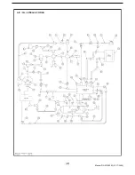
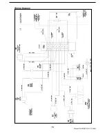
Page 52: ... 52 Manual P N 22189203 01 17 2005 Wiring Diagram ...

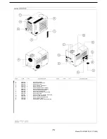
Page 53: ...486617 1 DECAL GENERAL DATA 60CFM G 54568795 1 DECAL HIGH PRESSURE AIR H 43215037 1 DECAL MAXIMUM SPEED J 22207872 1 DECAL VERTICAL GAGE LOCATION K 54672175 1 DECAL SWOOSH L 22184261 1 DECAL HYDRAULIC SUPPLY RETURN M 54640388 1 DECAL 20 IR MONOGRAM N 54568787 1 DECAL IMPROPER OPERATION P 54629902 1 DECAL 3 PART SAFETY Q 22197065 1 DECAL HORIZONTAL GAGE LOCATION 53 Manual P N 22189203 01 17 2005 ...

Reviews: