A
A
(Dwg. MHP1627)
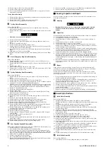
16. Install brake disc (694) on shaft spindle (678).
17. Install pin (696) in brake disc (695) and position brake disc (695) on brake disc
(694).
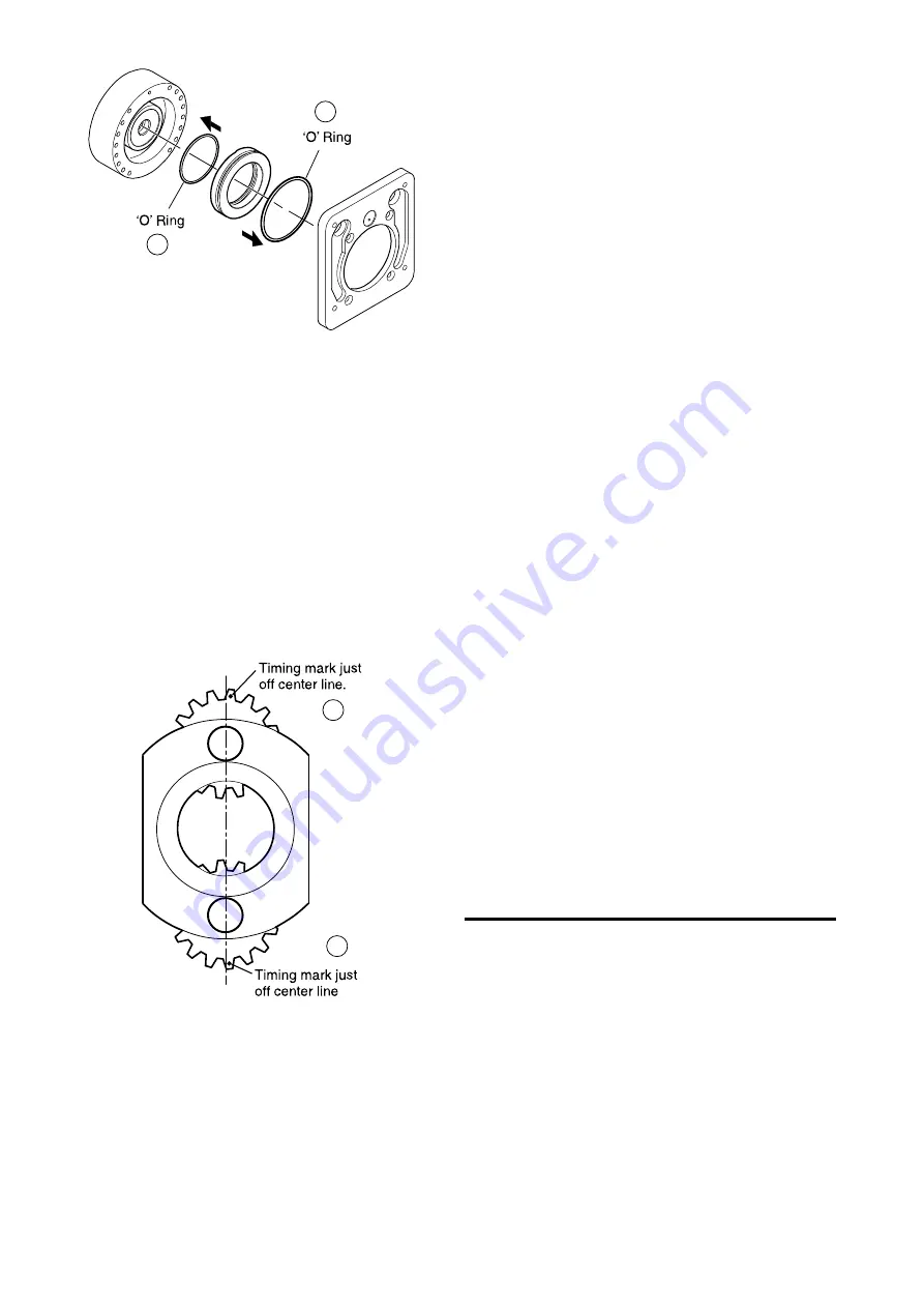
18. Install ‘O’ ring (698) in bore of coupling (699) in center groove.
19. Install coupling (699) and sleeve (700) on shaft spindle (678).
20. Install two mufflers (680) in motor flange (681).
21. Place four brake springs (701) in motor housing (331) using silicone to hold them
in place. DO NOT USE GREASE.
22. Lubricate and install ‘O’ ring (690) in recess on brake housing (689). Apply
Silicone AS310 (Silicomet) or equivalent to brake housing face.
23. Install motor flange (681) on gear housing (668) and secure with capscrews (682)
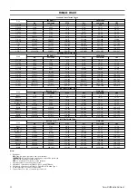
using Loctite® 243 on the threads. Refer to “TORQUE CHART” on page 12 for
torque requirements.
24. Apply Loctite® 574 to surface between motor flange (681) and motor housing
(331).
25. Ensure ‘O’ ring is installed in motor flange (681) prior to installing motor assembly
(300).
26. Install motor assembly (300) on motor flange ensuring springs stay in place and
pin (696), in brake disc (695), locates in hole in motor housing. Secure motor
assembly with four lockwashers (332) and capscrews (333). Tighten capscrews
(333) half a turn at a time to evenly compress brake springs (701). Refer to
“TORQUE CHART” on page 12 for torque requirements.
27. Install plugs (176) in gear housing (668).
28. Install reduction gear assembly on trolley side plate with capscrews (270) and
washers (271).
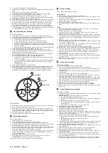
29. Install drive gear (136) with key (656) on planet support (655).
30. Install washer (135), washer (119) and capscrew (133) to secure drive gear (136).
A
A
(Dwg. MHP1560)
n
Hoist Suspension Assembly
Refer to Dwgs. MHP2970 and MHP2971.
1. Install a seal ring (150) and bearing (149) on each end of sprocket (152).
2. Position sprocket assembly in chain guide housing (151).
3. Install chain guide stop (146). Align pin holes and tap pins (147) into position
until flush with chain guide stop (146).
4. Install chain guides (143) and (144) on either side of chain guide housing using
connecting pins (145) for alignment.
5. Install seal rings (159) and (160), and bearings (158) and (161) on driving
sprocket (157).
6. Install central chain guide (141), seal bearing (162) and assembled driving
sprocket to chain guide (143) and chain guide stop (146).
7. Install caps (156), lockwashers (105) and capscrews (106) on connecting pins
(145).
8. Install cover (260) on central chain guide (141).
9. Install central chain guide (142) and seal bearing (162) on chain guide (144).
10. Install remaining caps (156), lockwashers (105) and capscrews (106) on
connecting pins (145).
11. Install screw rods (153), lockwashers (154) and nuts (115).
12. Insert suspension shafts (139) through central chain guides (141) and (142) and
trolley assemblies.
13. Install caps (113) and loosely secure with capscrews (106) and lockwashers (105)
on shafts (139).
14. Install limit switch assemblies (168).
n
Hoist Brake Installation
Refer to Dwg. MHP2972.
1. Position brake assembly (199) on brake cover (219).
2. Secure brake assembly with capscrews (201). Refer to ‘Torque Chart’
on page 12 for torque requirements.
n
Hoist Motor Installation
Refer to Dwgs. MHP2971 and MHP2973.
1. Carefully support motor assembly and position on central chain guide (142). Align
capscrew holes.
2. Secure motor with capscrews (406). Refer to “TORQUE CHART” on page 12 for
torque requirements.
n
Hoist Brake and Reduction Gear Installation
Refer to Dwgs. MHP2971 and MHP2972.
1. Lubricate and install ‘O’ rings (261) and (262).
2. Carefully support brake and reduction gear assembly and locate on screw rods
(153).
3. Secure brake and reduction gear assembly with lockwashers (154) and nuts (115).
Refer to “TORQUE CHART” on page 12 for torque requirements.
n
System Installation
1. Install hook and load chain on hoist.
2. Connect air lines, hoses and fittings.
3. Support hoist and trolley system with an adequate lifting system and install on
the end of support beam.
4. Carefully roll system onto beam and install beam rail stops.
5. Install chain bucket assembly on central chain guides (141) and (142). Refer to
Dwg. MHP2977. Secure with washers (481) and capscrews (482).
6. Repeat process to install second system.
n
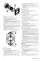
Four Function Pendant Assembly
Refer to Dwg. MHP1545 with emergency stop or MHP1577 without emergency stop.
1. Assemble protectors (506) and ‘O’ rings (511) and (505) on valves (509).
2. Insert valve (509) assemblies into pendant handle (514) and attachments (right)
(524) and (left) (523).
3. Install screws (515) in pendant handle and attachments (right) and (left).
4. Install balls (516), springs (517) and plugs (518) into pendant handle and
attachments (right) and (left).
5. Install plug (507) or emergency stop valve (508) into pendant handle.
6. Install fittings (327) into top of pendant handle and attachments (right) and
(left). Install lifting eye (501) into top of pendant handle.
7. Facing pendant handle operation side, place levers (503) such that lever direction
indicates ”UP” on left hand side and ”DOWN” on right hand side. Install pin (502)
ensuring pin inserts through levers and locates on opposite side of pendant
handle.
8. Install screw (504) in levers.
9. Lubricate and install ‘O’ rings (528) in recesses on sides of pendant handle (514).
10. Install attachment (right) (524) and (left) (523) to pendant handle (514) and
secure with washers (526) and capscrews (527) and (525). Install shorter screws
in back, longer screws in front.
11. Facing pendant handle operation side, place levers (522) such that lever direction
indicates ”LEFT” on left hand side and ”RIGHT” on right hand side. Install pins
(529) ensuring pins insert through levers and locate on side of pendant handle.
12. Install screw (504) in levers.
13. Install exhaust washer (513) in pendant handle and secure with retainer ring
(512).
14. Attach hoses to fittings located on top of pendant handle. Locate hoses to fittings
as shown in the ”INSTALLATION” section of Product Information Manual.
n
Testing
Prior to initial use, all extensively repaired hoists shall be load tested by or under the
direction of an
Ingersoll Rand
trained technician and a written report furnished
confirming the rating of the tested equipment.
n
Trolley Operational Test
To ensure proper operation of the trolley, mount the system and conduct the
following:
1. Verify that pendant to trolley hoses are properly attached and that trolley
movement agrees with the pendant lever arrows.
2. Operate trolley
without
a load on the system. Verify trolley operates smoothly
along entire length of the beam.
3. Operate trolley
with
a load on the system. Verify trolley operates smoothly along
entire length of the beam.
n
Limit Switches
Operate hoist through three complete cycles to ensure consistent limit switch
operation /- 2 feet (0.6 m) of set points. Refer to ”Limit Switch Adjustment”
procedure in Product Information Manual to establish set points.
10
Form MHD56416 Edition 1


