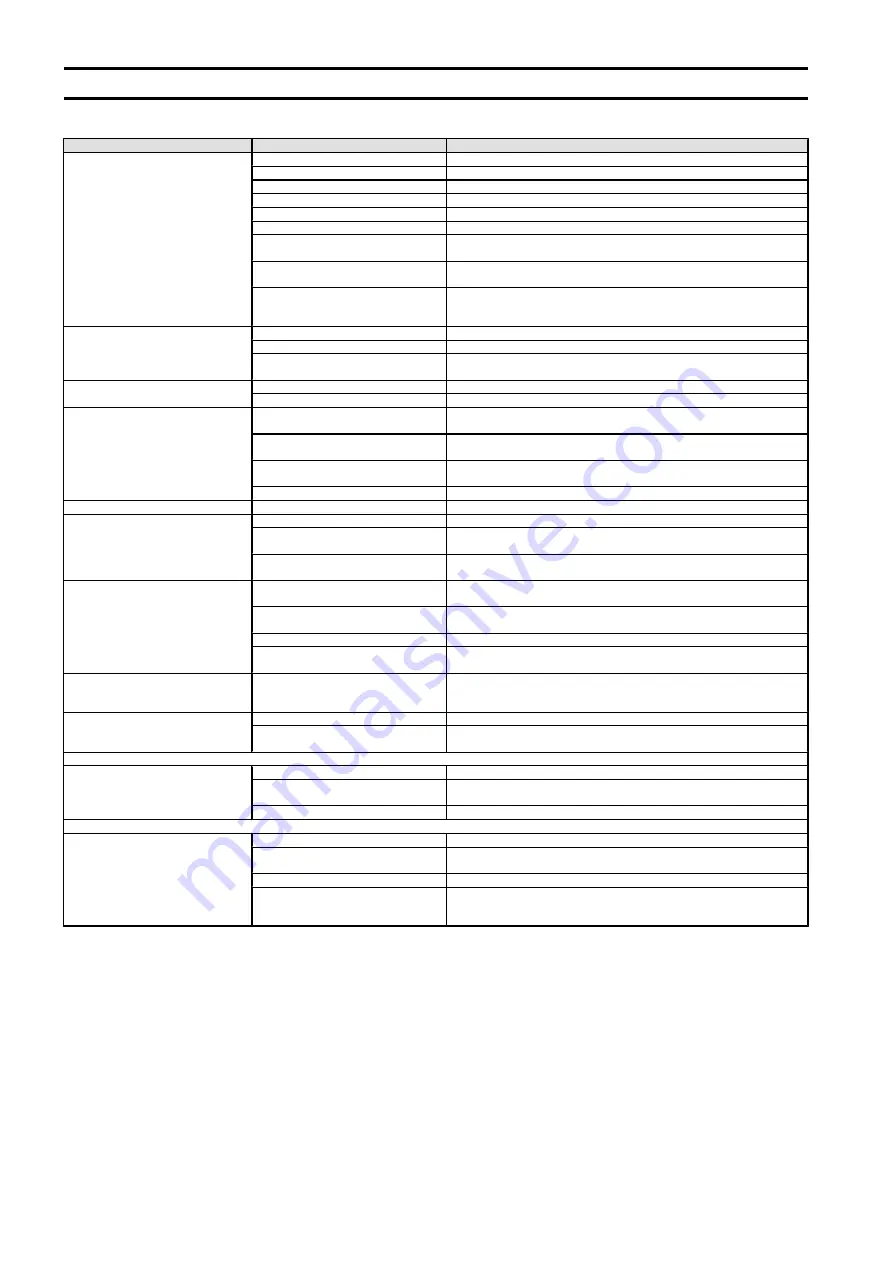
TROUBLESHOOTING
This section provides basic troubleshooting information. Determination of specific causes to problems are best identified by thorough inspections performed by personnel
instructed in safety, operation and maintenance of this equipment. The chart below provides a brief guide to common winch symptoms, probable causes and remedies.
SYMPTOM
CAUSE
REMEDY
Winch will not operate.
Insufficient or no air supply to winch.
Check air supply line connections and hoses.
Winch is overloaded.
Reduce load to within rated capacity.
Disc brake does not release.
Inspect brake piston seals and replace if seals appear to be leaking.
Drum brake does not release.
Refer to ʽAdjustmentsʽ in “MAINTENANCE” section on page 7.
Emergency stop valve engaged.
Reset emergency stop valve.
Motor may be damaged.
Disassemble and clean the motor and replace any broken or damaged parts.
Air leak.
Check hose and fitting connections. Inspect hose(s) for breaks. Tighten fittings and
repair or replace hoses as necessary.
Overload device engaged.
Reduce load to within rated capacity of winch. If overload device cannot be reset,
contact factory.
Air lines freeze due to water in air supply.
Install or drain air system moisture traps, moisture collecting air receivers and
compressor aftercoolers. After corrective action has been taken, disconnect lines at
winch inlet and purge with clean, dry air or nitrogen.
Load continues to move when winch is
stopped.
Brake is slipping.
Check brake friction discs and automatic band drum brake wear.
Winch is overloaded.
Reduce load to within rated capacity.
Winch motor controls sticking.
Check pendant/throttle levers spring return to normal (neutral) position when
released.
Winch hauls-in but does not payout.
Lower limit switch activated.
Raise load and check limit switch settings.
Slack line detector activated.
Determine cause of slack line and rectify problem.
Winch does not lift load or does not lift
rated capacity. Winch does not lift load.
Motor may be damaged.
Remove and disassemble motor as described in ‘’ on page 7. Examine all parts
and replace any that are worn or damaged.
Insufficient air supply.
Verify air supply pressure and volume at winch inlet meets the requirements listed
in the “SPECIFICATIONS” section in Product Information Manual. Clean air line filter.
Brake is not releasing.
Check brake release pilot hole is not restricted. Check seals on cylinder piston are
not damaged. Brake will start to release at 50 psig (3.5 bar/350 kPa).
Winch is overloaded.
Reduce load to within rated capacity.
Oil leak from motor end of winch.
Reduction assembly is leaking.
Disassemble winch and inspect reduction assembly seals.
Throttle or pendant lever moves but winch
does not operate.
Motor may be damaged.
Disassemble, inspect and clean motor. Replace any broken or damaged parts.
Insufficient air supply.
Ensure air pressure at winch inlet is at least 90 psig (6.3 bar/630 kPa) at rated volume.
Clean air line filter.
Air leak.
Check hose and fitting connections. Inspect hose(s) for breaks. Tighten fittings and
repair or replace hoses as necessary.
Winch runs slow.
Improper hose or fitting sizes.
Check fittings, connections and hoses for correct size and length. Replace parts that
may cause restricted air flow. Inspect air line filter.
Motor may be damaged.
Remove and disassemble motor as described in ‘’ on page 7. Inspect all parts and
replace all worn or damaged parts.
Brake(s) not releasing.
Refer to brake sections below.
Insufficient air supply.
Verify air supply pressure and volume at winch inlet meets the requirements. Refer
to “SPECIFICATIONS” section in Product Information Manual. Clean air line filter.
Air lines freeze.
Water in air supply.
Install or drain air system moisture traps, moisture collecting air receivers and
compressor aftercoolers. After corrective action has been taken, disconnect lines at
winch inlet and purge with clean, dry air or nitrogen.
Throttle or pendant lever moves but winch
does not operate.
Motor may be damaged.
Disassemble, inspect and clean motor. Replace any broken or damaged parts.
Insufficient air supply.
Ensure air pressure at winch inlet is at least 90 psig (6.3 bar/630 kPa) at rated volume.
Clean air line filter.
Automatic Band Brake:
Brake cylinder will not release.
Band brake out of adjustment.
Adjust band brake to maintain correct cylinder stroke.
Leaking cylinder seals.
If air is noticed escaping from cylinder breather when attempting to release brake,
replace or repair cylinder.
Dirty filter in air supply.
Clean or replace filter.
Automatic Disc Brake:
Brake fails to release.
Low air supply pressure.
Ensure air pressure at inlet to disc brake is at least 60 psig (3.4 bar/340 kPa).
Leaking piston seals.
Inspect brake breather. If air escapes from brake breather when attempting to
release brake, replace brake seals.
No release pressure at brake port.
Check for proper operation of winch controls.
Sticking brake piston.
Apply 60 psig (3.4 bar/340 kPa) to brake release port and check for brake disc
movement. (Brake discs can be viewed through brake breather hole.) If brake discs
do not move, disassemble and inspect disc brake as described in ‘’ on page 7.
6
Form MHD56305 Edition 4


