background image

10

INSTALLATION

Prior to installing the winch, carefully inspect it for possible
shipping damage.
Winches are supplied fully lubricated from the factory. Check
oil levels and adjust as necessary before operating winch. Refer
to “LUBRICATION” section for recommended oils.

CAUTION

• Owners and users are advised to examine specific, local or
other regulations, including American National Standards
Institute and/or OSHA Regulations which may apply to a
particular type of use of this product before installing or
putting winch to use.

Mounting

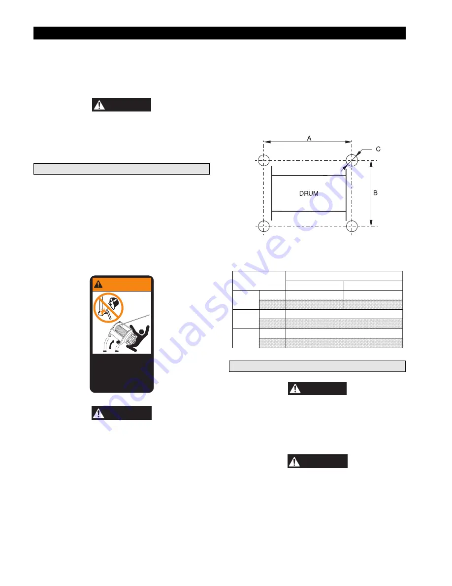
Refer to Dwg. MHP0124 and Table 1.
Care must be taken when moving, positioning or mounting the
winch. Ensure that the winch, when lifted, will be properly
balanced. Determine the weight of the winch by referring to the
“SPECIFICATIONS” section. Lift the winch 3 to 4 inches (75
to 100 mm) off the ground. Verify winch is balanced and secure
before continuing lift.
Mount the winch so the axis of the drum is horizontal and that
the motor vent cap is not more than 15° off top vertical center. If
the winch is to be mounted in an inverted position, the motor
case must be rotated to position the vent cap at the top and
adequate clearance must be provided for control valve operation.

WARNING

Welded mountings
can fail.
Can cause severe
injury or death.
Do not weld, braze or
solder to winch.

71270813

WARNING

• Winch frame material is not suitable for welding. FA5AMR
winches must only be mounted by bolting to a suitable
foundation. Do not attempt to mount the winch by welding to
a foundation structure.

1.

The winch mounting surface must be flat and of sufficient
strength to handle the rated load plus the weight of the
winch and attached equipment. An inadequate foundation
may cause distortion or twisting of the winch uprights and
side rails resulting in winch damage.

2.

Make sure the mounting surface is flat to within 1/32 inch
(0.8 mm). Shim if necessary.

3.

Mounting bolts must be 3/4 inch-NC (18 mm) Grade 8 or
better. Use self-locking nuts or nuts with lockwashers.

4.

Tighten mounting bolts evenly and torque to 380 ft lbs (515
Nm) for dry thread fasteners. If the fasteners are plated,
lubricated or a thread locking compound is used, torque to
280 ft lbs (380 Nm).

5.

Maintain a fleet angle between the lead sheave and winch
of no more than 1-1/2°. The lead sheave must be on a
center line with the drum and, for every inch (25 mm) of
drum length, be at least 1.6 feet (0.5 metre) from the drum.
Refer to Dwg. MHP0498.

6.

Do not weld to any part of the winch.

(Dwg. MHP0124)

Table 1: Mounting Bolt Hole Dimensions

Dimension

Drum Length (inches)

12

24

“A”

in.

17.89

29.89

mm

455

760

“B”

in.

22

mm

559

“C”

in.

0.81

mm

21

Wire Rope

CAUTION

• Maintain at least 4 tight wraps of wire rope on the drum at
all times. Refer to Dwg. MHP0498.

Install the winch such that the wire rope, when at the take-off
angle limits, shown in Dwg. MHP1404, does not contact the
mounting surface.

DANGER

• Exceeding the wire rope take-off angles will cause the wire
rope to come into contact with the winch frame supports
resulting in damage to the wire rope and winch.

Summary of Contents for ManRider force5 FA5AMR-LAK1

Page 1: ...and that are identified for personnel lifting by a permanent nameplate attached to the winch at the factory Always operate inspect and maintain this winch in accordance with American National Standards Institute Safety Code ASME B30 7 and any other applicable safety codes and regulations Refer all communications to the nearest Ingersoll Rand Material Handling Office or Distributor Form MHD56115 Ed...

Page 2: ...erating Checks 13 Operation Winch Controls 14 Brakes 16 Inspection Records and Reports 17 Wire Rope Reports 17 Frequent Inspection 17 Periodic Inspection 18 Winches Not in Regular Use 18 Inspection Report Form 19 Troubleshooting 20 Lubrication 21 Maintenance Thermoplastic Coating 23 Adjustments 24 Disassembly 24 Cleaning Inspection and Repair 29 Assembly 30 Testing 37 Parts Section Winch Parts Dra...

Page 3: ...ledge that includes 1 Proper and safe use and application of mechanics common hand tools as well as special Ingersoll Rand or recommended tools 2 Safety procedures precautions and work habits established by accepted industry standards Ingersoll Rand cannot know of or provide all the procedures by which product operations or repairs may be conducted and the hazards and or results of each method If ...

Page 4: ...ns automatically terminates for any of the following reasons 1 Winch does not meet other applicable codes or standards 2 Winch is not part of an approved system 3 Winch is not properly maintained in a new condition with all parts intact and properly adjusted 4 Winch is used in applications not approved by codes and regulations or applications inconsistent with manufacturer s operating and maintena...

Page 5: ...merican National Safety Standard ASME B30 7 and are intended to avoid unsafe operating practices which might lead to injury or property damage Ingersoll Rand recognizes that most companies who use winches have a safety program in force at their facility In the event that some conflict exists between a rule set forth in this publication and a similar rule already set by an individual company the mo...

Page 6: ... rope fleet angle Not to exceed 1 1 2 1 1 2 degrees Drum locking pin Not Allowed Disengaging clutch Not Allowed Drum guard Required Overload protection Optional required to meet CE European Community directives Travel limit switch Optional owner responsibility Emergency Lowering Not Required Required Design approval by regulatory or certifying authority Required Witness tests at time of manufactur...

Page 7: ...ngaged This ensures the brake will respond quickly to hold the load when winch operation stops Operation of the winch in the payout direction directs pressurized air to the disc brake diaphragm to overcome spring tension and release the brake When the payout operation is complete the air is vented and the brake is automatically applied The drum band brake operates by applying a friction force betw...

Page 8: ... Machinery Directive not rated as a utility winch Muffler Overload Device Drum Guard CE Documentation Main air supply emergency shutoff J Overload Device K K6U footprint base L Limit Switch upper and lower P Emergency Stop Device 7 Drum grooving specify rope size in sixteenths 7 7 16 inch wire rope Type Approval A American Bureau of Shipping ABS Type Approval N Det Norske Veritas DNV Type Approval...

Page 9: ... mm Drum Barrel Diameter 12 75 inches 324 mm 12 75 inches 324 mm Drum Flange Diameter 24 25 inches 616 mm 24 25 inches 616 mm Winch Net Weight without wire rope Model lbs kg Model lbs kg FA5AMR SMK1 1 170 532 FA5AMR SMK2 1 145 520 FA5AMR SAK1 1 175 534 FA5AMR SAK2 1 175 534 FA5AMR LMK1 1 363 620 FA5AMR LMK2 1 380 627 FA5AMR LAK1 1 390 632 FA5AMR LAK2 1 390 632 Winch Wire Rope Storage Capacities fe...

Page 10: ...ed by bolting to a suitable foundation Do not attempt to mount the winch by welding to a foundation structure 1 The winch mounting surface must be flat and of sufficient strength to handle the rated load plus the weight of the winch and attached equipment An inadequate foundation may cause distortion or twisting of the winch uprights and side rails resulting in winch damage 2 Make sure the mountin...

Page 11: ...tio 3 4 18 mm wire rope must be used Installing Wire Rope Refer to Dwg MHP1317 1 Cut wire rope to length and fuse end to prevent fraying of strands in accordance with the wire rope manufacturer s instructions 2 Feed the end of the wire rope into the wire rope anchor hole in the drum and pull through approximately three feet 1 metre of wire rope 3 Forming a large loop with the wire rope insert the ...

Page 12: ... performance Foreign particles moisture and lack of lubrication are the primary causes of premature motor wear and breakdown Using an air filter lubricator and moisture separator will improve overall winch performance and reduce unscheduled down time The air consumption is 600 scfm 17 cu m min at rated operating pressure of 90 psig 6 3 bar 630 kPa at the winch motor inlet If air supply varies from...

Page 13: ...alanced before personnel are allowed to occupy the platform Before elevating or lowering personnel the following conditions shall exist a Hoist wire rope shall be free of kinks b Multiple part lines shall not be twisted around each other c The primary point of wire rope attachment shall be centered over the platform so that the platform will not oscillate when lifted d If there is a slack wire rop...

Page 14: ...l will enter and leave the platform the use of safety equipment signals and the lift chart information NOTICE This meeting shall be held prior to the beginning of personnel hoisting operations at each new work location and thereafter for any new employees assigned to the operation Winch Controls A spring loaded motor mounted manual throttle control valve is supplied as a standard feature on these ...

Page 15: ...ncy Stop Device Optional feature Refer to Dwg MHP0695 The emergency stop device used on Winch Mounted Manual Throttle Control equipped winches is located at the air inlet of the winch When activated winch drum rotation will immediately cease To activate the emergency stop valve conduct one of the following 1 Depress push down red palm valve 2 Press emergency stop button on remote control pendant o...

Page 16: ...t must be disassembled inspected and repaired WARNING If the brake is disassembled the friction and separator plates must be correctly installed as described in the MAINTENANCE section of this manual Failure to correctly install the friction and separator plates can cause injury and or property damage Automatic Drum Brake Optional feature The automatic drum brake is a spring applied air released e...

Page 17: ...s in instability or causes permanent deformation of any component 4 A visual inspection of the winch personnel platform and rigging shall be conducted immediately after the test lift Wire Rope Reports Records should be maintained as part of a long range wire rope inspection program Records should include the condition of wire rope removed from service Accurate records will establish a relationship...

Page 18: ...nal evidence indicates damage disassemble as required to conduct a detailed inspection Inspect gears shafts bearings sheaves springs and covers Replace worn or damaged parts Clean lubricate and reassemble 6 BRAKES Individually test brakes installed to ensure proper operation Brakes must hold a 100 rated load at mid drum without slipping If indicated by poor operation or visual damage disassemble a...

Page 19: ... Standards and codes of practice If in doubt about an existing condition contact the nearest Ingersoll Rand distributor or the factory for technical assistance COMPONENT CONDITION CORRECTIVE ACTION NOTES Pass Fail Repair Replace Uprights and Sideframes Drum Band Brake 125 Load Test Disc Brake 125 Load Test Drum Band Brake Visual Inspection Disc Brake Visual Inspection Motor Controls Air System Fas...

Page 20: ...y Stop valve Overload Device engaged Reduce load to within rated capacity of winch If Overload Device cannot be reset contact factory Air leak Check hose connections Check hose lines for wear or damage Replace worn or damaged hoses Motor runs hot or makes excessive noise during operation Improper lubrication Check oil level Set lubricator to provide a minimum of 6 drops per minute Damaged or broke...

Page 21: ...onmentally safe manner Reduction Gear and Disc Brake Lubrication Refer to Dwg MHP0501 The reduction gear and disc brake are filled with oil to the correct level prior to shipment from the factory Check oil level before initial winch operation These components are splash lubricated by the oil in the housing and have no other means of lubrication It is therefore important to use high quality Extreme...

Page 22: ...capacity for the winch motor is 3 quarts 2 8 litres Add oil through the filler opening until oil flows from the level plug hole The motor should be level checked daily or at the start of each shift after any accumulated water has been drained off When motors are operated in temperatures below freezing wait long enough at end of shift for water to separate from oil but not long enough for it to fre...

Page 23: ...moplastic coating is an extremely tough and durable coating designed to take the toughest treatment without chipping or peeling Special steps must be taken to protect the coating when parts are removed replaced and if excessive environmental or operational conditions have damaged the coating Cleaning Parts The area to be coated must be clean and free from loose coating Remove any surface corrosion...

Page 24: ...rum 2 Raise handle 135 to free brake bands 136 and 137 3 Remove cotter pin 139 and pin 138 4 Rotate brake link stud 141 clockwise to increase brake torque 5 Install pin 138 and check adjustment NOTICE If brake band cannot be adjusted to hold the rated load replace the brake band assembly 6 Adjust brake so when brake handle locks goes over center brake will hold rated load 7 Install cotter pin 139 ...

Page 25: ... anchor 63 and store for reassembly 2 Relieve pressure in the air lines and winch air components by operating the winch control several times after the air supply has been turned off WARNING Shut off bleed down and disconnect the air supply line before performing any disassembly procedures 3 Disconnect and tag the air lines 4 To drain oil refer to LUBRICATION section 5 Remove the capscrews and nut...

Page 26: ...lve 1 Disconnect the air line fittings at the shuttle valve body 479 2 Disconnect the air inlet line at the valve inlet On units equipped with an emergency stop valve disconnect air inlet at the valve 3 To separate valve from motor alternately loosen capscrews 442 on adapter 440 Capscrews and washers 434 cannot be removed until adapter is separated from valve body 410 Separate valve as an assembly...

Page 27: ...onduct steps 6 through 8 with the following exceptions a Step 6a applies to both ends of the valve shaft therefore remove pins 406 and shims 444 from both ends of valve shaft 401 b Step 7a does not apply to the Pendant Operated Pilot Control Valve Skip this step and proceed to step 7b Live Air Throttle Valve Disassembly Optional feature Refer to Dwg MHP1380 NOTICE Match mark throttle valve parts t...

Page 28: ... further disassembled into two wearing plates and the sprag cage Automatic Drum Band Brake Disassembly Optional feature Refer to Dwg MHP1281 1 Loosen jam nut 117 closest to plunger 114 Turn capscrew 120 counterclockwise until disconnected from plunger 2 Disconnect air line from brake cylinder 121 With the aid of a strap wrench remove brake cylinder 121 and components as an assembly by turning brak...

Page 29: ...rnal roller bearings 50 in each gear from falling out during removal e Note the position and quantity of the washers 84 85 and 86 in each gear assembly Keeping the washers separated by assembly will assist in reinstallation NOTICE If gear clearance is not within specification 0 005 to 0 032 inch 0 1 to 0 8 mm as determined in Step 4a correct location quantity of washers 84 85 and 86 must be determ...

Page 30: ...31 on a work bench with the oil slinger 230 down and slide the sleeve 232 with tang up on the crankpin 6 Slide connecting rod bushing 233 over the sleeve 232 and first connecting rod ring 234 with the chamfer up 7 Install the connecting rods 206 in the same order as removed with all feet pointing in the same direction using the first connecting rod ring 234 to hold one side of the connecting rod f...

Page 31: ...1 Nm Valve Body Assembly Refer to Dwg MHP1408 Pendant Pilot Operated Valve and MHP1407 Lever Operated Valve 1 Facing the flats of the valve shaft 401 slide sleeve 408 onto shaft with the flat end of sleeve on the left and the angled 45 end of sleeve on the right Center sleeve on shaft 2 Align the center hole in sleeve with offset hole 18 below centerline in shaft and install setscrew 407 to attach...

Page 32: ...capscrew 465 and install in hole located between brake valve assembly ports in valve body 410 Tighten capscrew and ensure spring washer locks brake assembly s 413 and or pin s 412 in place Dwg MHP1023 12 Secure in place using retainer ring 429 Remove cotter pin installed in step 8 NOTICE The flats on shaft 401 must be facing the left or valve side of the valve body 410 13 On opposite side of valve...

Page 33: ...assembly 423 end face Secure in place with cotter pin 414 with ends bent back to hold in place 2 Press pin 463 into handle 449 until one end protrudes approximately 1 16 inch 1 6 mm 3 Slide O ring 460 down handle into groove and lubricate 4 Slide spring 462 over handle and onto pin 5 Insert this assembly up through the bottom of cross shaft 461 The bottom is the side with the groove for locating p...

Page 34: ...ing care not to dislodge O ring 5 Lubricate O ring 457 and install in seal cup face groove NOTICE The slot in the seal cup viewed from valve cap cover end must be located at the bottom when installed correctly This is required to provide clearance for the shaft 401 pins 406 6 Coat external mating sleeve surface of cylinder 451 with Loctite 609 and press into valve cap 438 CAUTION Ensure cylinder 4...

Page 35: ...NPT holes in the end cover with counterbore marks on the housing mating flange Secure in place by evenly installing sixteen capscrews 32 Torque capscrews to 60 ft lbs 81 Nm 9 Cover the reduction gear to prevent dirt and contaminants from entering assembly and place in a safe place until ready for assembly to winch uprights Winch Assembly Refer to Dwg MHP1410 NOTICE Unless otherwise stated capscrew...

Page 36: ...et Attach band assembly 104 to bracket 106 using three capscrews 101 spacers 102 and spacer tubes 103 Torque capscrews to 55 ft lbs 75 Nm 6 Install pivot bar 119 and capscrew 120 through lower flange of brake band assembly 104 At lowest point of threads place a bead of Loctite 680 and install jam nut 117 fully Jam nut threads must become coated with sealant Install second jam nut 117 to approximat...

Page 37: ... to elbow fitting 13 Winch drum must rotate freely in the haul in direction and must not rotate in the payout direction unless air is applied to the brake when assembled properly Dwg MHP1197 Testing Operational Test Prior to initial use all new altered or repaired winches shall be tested to ensure proper operation 1 Check oil level in motor reduction gear assembly and disc brake are correct Top of...

Page 38: ...l Valve Assembly Parts Drawing MHP1408 50 Pendant Operated Pilot Control Valve Assembly Parts List 51 Remote Pendant Assembly Parts Drawing MHP0934 52 Remote Pendant Assembly Parts List 53 Shuttle Valve Assembly Parts Drawing MHP1409 54 Shuttle Valve Assembly Parts List 55 Emergency Stop and Overload Assembly Parts Drawing MHP1188 56 Emergency Stop and Overload Assembly Parts List 57 Control Valve...

Page 39: ...39 WINCH CROSS SECTION DRAWING ...

Page 40: ...40 WINCH ASSEMBLY PARTS DRAWING ...

Page 41: ...23230 75 43 Gear Planet 3 23893 80 Capscrew 6 71113161 44 Thrust Washer 1 20406 81 Capscrew 8 71264709 67 Input Carrier Assembly 1 1 23897 82 Corner Bar 4 21882 45 Intermediate Sun Gear 1 23894 83 Roll Pin 3 71267793 46 Retainer Ring 2 71113278 84 Washer 0 123 thickness Refer to Note 3 71146807 47 Carrier Planet 1 23898 85 Washer 0 06 thickness 71113229 49 Pin Planet 3 20386 86 Washer 0 092 thickn...

Page 42: ...42 MOTOR ASSEMBLY PARTS DRAWING ...

Page 43: ...ylinder Liner 5 K5B L505 47 244 O Ring 1 20A11CM248 209 Head Gasket 1 Set 26228 246 Grease Fitting 1 53095 210 Vent Cap Assembly 1 K5B A303 247 Rotary Valve Housing 1 K5B 545 213 Eye Bolt 2 KU 888 248 Gasket 1 K5B 547 216 Mounting Flange 1 K5B 502 250 Rotary Valve 1 K5B 526EQ R 217 Motor Housing 1 K5B 501A 251 Seal Ring 1 Set K5B 607A 218 Pipe Plug 1 71263297 252 Bearing 1 50138 225 Pipe Plug 2 54...

Page 44: ...44 DISC BRAKE ASSEMBLY PARTS DRAWING ...

Page 45: ...ew 8 71264691 11 Spacer 2 19007 74 Washer 8 71274807 12 Outer Race 1 22032 79 Valve Exhaust 1 71047898 13 Friction Plate 5 71126874 80 Elbow Fitting 1 24141 14 Separator Plate 6 22033 82 Corner Bar 2 21882 Sideframe Brake Hose 65 Short Drum 12 inch 1 24674 75 Short Drum 12 inch hose length 63 inches 1 23230 63 Long Drum 24 inch 24675 Long Drum 24 inch hose length 75 inches 23230 75 Model Driver Op...

Page 46: ... Spacer Tube 3 21891 120 Capscrew 1 71326805 104 Band Assembly 1 25144 121 Cylinder 1 26138 105 Spacer 1 23029 122 O Ring 1 52536 106 Brake Bracket 1 22984 123 Piston 1 25534 107 Capscrew 2 71298921 124 Spring 1 71299721 108 Cylinder Rod 1 23885 125 Cover 1 25392 109 O Ring 1 71049423 126 Retainer Ring 1 71126668 110 O Ring 1 52662 127 Spring 1 71299713 111 Retainer Ring 1 54136 128 Washer 1 71145...

Page 47: ...68 Upright Motor End 1 25567 25567CH 112 Capscrew 4 71335459 131 Washer 4 71334411 134 Pivot Nut 1 2445 2445CH 135 Brake Handle 1 26388 26388CH 136 Rear Brake Band Assembly 1 26345 26345CH 137 Front Brake Band Assembly 1 26342 26342CH 138 Pin 1 4303 S 4303 SCH 139 Cotter Pin 1 51996 141 Brake Link Stud 1 4115 4115CH 142 Washer 1 71334379 143 Bushing 2 71334403 144 Cotter Pin 1 50965 145 Adapter Pl...

Page 48: ...48 LEVER OPERATED CONTROL VALVE ASSEMBLY PARTS DRAWING ...

Page 49: ...Capscrew 2 71261747 450 Valve Cap 1 23607 419 Gasket 1 23744 460 O Ring 1 71146963 420 Exhaust Poppet 1 23516 461 Cross Shaft 1 23746 421 Plug 1 51897 462 Spring 1 71146948 422 Spring 2 71138028 463 Pin 1 71146955 423 Inlet Poppet Assembly 2 24139 464 Detent Plate 1 23748 424 Gasket 1 71264725 465 Capscrew 3 53807 425 Fitting Elbow 71262299 469 Knob 1 71138051 426 O Ring 2 52662 470 Capscrew 2 713...

Page 50: ...50 PENDANT OPERATED PILOT CONTROL VALVE ASSEMBLY PARTS DRAWING ...

Page 51: ...454 Piston 2 23596 419 Gasket 1 71303861 455 O Ring 2 71145650 420 Exhaust Poppet 1 23516 456 Seal Cup 2 23597 421 Plug 1 51897 457 O Ring 2 71138234 422 Spring 2 71138028 458 Setscrew 2 71148779 423 Inlet Poppet Assembly 2 24139 459 Retainer Spring 2 24041 424 Gasket 1 71264725 465 Capscrew 3 53807 425 Fitting Elbow 71262299 470 Capscrew 2 71303671 426 O Ring 2 52662 471 Seal Washer 2 71303838 42...

Page 52: ...52 REMOTE PENDANT ASSEMBLY PARTS DRAWING ...

Page 53: ...42 625 Pin Dowel 2 71261341 Spring Emergency Stop 1 71261390 626 Cover 1 24443 641 Button 3 24155 628 Gasket 2 71044960 642 O Ring 3 50557 631 Fitting 2 71044937 643 Label 1 Set 71261309 632 Spring 2 71263081 645 Pendant Hose length 6 ft 1 26028 633 Fitting 2 71273114 646 Pendant Extension Assembly 1 24259 XX Recommended spare Pendant Assembly includes items 620 through 645 Pendant Extension Assem...

Page 54: ...54 SHUTTLE VALVE ASSEMBLY PARTS DRAWING ...

Page 55: ...g 1 52662 482 Elbow Fitting 2 71262091 638 Swivel 1 24433 483 Tube Fitting 1 71044937 Lever Operated Air Valve 479 Shuttle Valve Body 1 23739 494 Nipple Fitting 71262117 418 Capscrew 2 71261747 495 Elbow Fitting 71267173 419 Gasket 1 23744 629 Roll Pin 2 71039374 425 Elbow Fitting 71262299 630 Pin 1 71146674 435 Plug 71069009 Recommended spare Tubing colors noted on Dwg MHP0764 are for reference o...

Page 56: ...56 EMERGENCY STOP AND OVERLOAD ASSEMBLY PARTS DRAWING ...

Page 57: ...6 Body 1 24200 528 Capscrew 4 71138077 530 Poppet Assembly 1 25837 531 O Ring 1 71137970 534 O Ring 2 50846 535 Ball 1 71126833 536 Spring 1 71263875 537 O Ring 1 71126825 538 Poppet Rod Assembly 1 25838 539 Spring 1 71261945 540 Rod Emergency Stop 1 24255 541 O Ring 1 71303978 542 Poppet Guide 1 24256 543 O Ring 1 71137962 544 Retainer Ring 1 71157507 545 Palm Valve Knob 1 24257 546 Label 1 71266...

Page 58: ...y 1 K5B 944 304 Lockwasher 2 51581 317 Gasket 1 K5B 275 305 Valve Body Retainer 1 K5B 1110AP 318 Flange 1 KK5B 276SP 319 Fitting Elbow Swivel 1 71328561 306 Spring Retaining Stud 1 K5B 553 321 Gasket 1 K5B 547 307 Latch 1 K5B 869AP 331 Capscrew 4 71325039 308 Roll Pin 1 HLK 20 523 Fitting Elbow 1 71273676 309 Pipe Plug 2 71263297 524 Fitting Nipple 1 71057483 310 Fitting Bushing 1 51814 525 Muffle...

Page 59: ...ow Fitting 4 71015457 322 Hose End 4 54738 323 Hose 2 54737 324 Elbow Fitting 1 52182 325 Hose End 2 51029 326 Hose 1 50923 327 Exhaust Cover 1 251P2559A 329 Lockwasher 5 50181 Add hose length feet metres Maximum length 20 feet 6 metres Contact Ingersoll Rand for information on control suitability for lengths greater than 20 feet 6 metres Metres are for reference only order quantities in feet ...

Page 60: ...DESCRIPTION OF PART QUANTITY TOTAL PART NUMBER Motor Muffler and Fittings 710 Muffler 1 50594 711 Elbow Fitting 1 71106439 712 Reducer 1 71057459 Control Valve Muffler and Fittings 713 Nipple Fitting 1 71311260 714 Elbow Fitting 1 54299 715 Muffler 1 71264360 ...

Page 61: ...2 71261739 4 593 Washer As required 71296800 594 Capscrew 1 71306443 595 Bracket 1 26367 596 Pin 1 26376 597 Capscrew 2 71306435 598 Nut 2 71335616 Drum Guard Assemblies on Winches with Manual Drum Band Brake includes Items 74 and 590 through 598 Manual Band Brake Short Drum 12 inch 1 26392 Manual Band Brake Long Drum 24 inch 26393 Drum Guard Assemblies on Winches with Automatic Drum Band Brake in...

Page 62: ...ION OF KIT QTY TOTAL PART NUMBER DESCRIPTION OF KIT QTY TOTAL PART NUMBER Adapter Rail Kit for FA5A Short Drum to K6U Foot Print 1 24333 Adapter Rail Kit for FA5A Long Drum to K6U Foot Print 1 24332 ITEM NUMBER DESCRIPTION OF PART QUANTITY TOTAL PART NUMBER 575 Filter 1 F42 0B 000 576 Pipe Nipple 1 51670 577 Regulator 1 R30 0B G00 578 Pipe Nipple 3 51704 579 Pipe Bushing 2 Contact factory 580 Lubr...

Page 63: ...ck Oil Level Notice 1 71107148 351 Nameplate 1 71108849 343 Warning Label 1 71124887 352 Drive Screws 8 50915 344 Air Supply Label 1 sheet 71295240 354 Do Not Weld Label 2 71270813 345 Exhaust Label 355 IR Logo Label 12 inch Drum 1 71106272 346 Oil Level Label 347 Oil Drain Label IR Logo Label 24 inch Drum 71109102 348 Oil Fill Label 349 Product Label 12 inch 1 71111785 356 IR Monogram Label 1 711...

Page 64: ...64 SERVICE NOTES ...

Page 65: ...65 SERVICE NOTES ...

Page 66: ... 206 624 0466 Fax 206 624 6265 or Ingersoll Rand Material Handling Douai Operations 111 avenue Roger Salengro 59450 Sin Le Noble France Phone 33 3 27 93 08 08 Fax 33 3 27 93 08 00 PARTS ORDERING INFORMATION The use of other than Ingersoll Rand Material Handling replacement parts may adversely affect the safe operation and performance of this product For your convenience and future reference it is ...

Page 67: ...iginal user its Hoists and Winches Products to be free of defects in material and workmanship for a period of one year from the date of purchase I R will repair without cost any Product found to be defective including parts and labor charges or at its option will replace such Products or refund the purchase price less a reasonable allowance for depreciation in exchange for the Product Repairs or r...

Page 68: ...5 9040 Fax 514 695 0963 British Columbia 201 6351 Westminster Hwy Richmond B C V7C 5C7 Phone 604 278 0459 Fax 604 278 1254 Latin America Operations Ingersoll Rand Production Equipment Group 730 N W 107 Avenue Suite 300 Miami FL 33172 3107 Phone 305 559 0500 Fax 305 559 7505 Europe Middle East and Africa Ingersoll Rand Material Handling Douai Operations 111 avenue Roger Salengro 59450 Sin Le Noble ...

Reviews: