15
(Dwg. MHP0696)
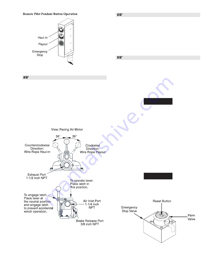
Winch Mounted Full Flow Throttle Control Valve
Optional feature. Refer to Dwg. MHP0566.
The spring loaded, live air, manual control throttle valve mounts
to the air motor.
As viewed from the air motor end, move the control throttle
handle to the right (clockwise) to payout wire rope and to the
left (counterclockwise) to haul-in wire rope. Avoid sudden
movements of the control valve to ensure smooth operation of
the winch.
When winch is not in use, engage handle latch to prevent
inadvertent movement of the control throttle.
Winch Mounted Full Flow Throttle Control Valve
(Dwg. MHP0566)
Remote Full Flow Throttle
Optional feature. Refer to Dwg. MHP0161.
Provides for the remote mounting of the winch control at a fixed
location at up to 20 feet (6 metres) away from the winch motor.
Air hoses connect the throttle to the winch motor to provide
winch operation.
Move the control throttle handle to the right (clockwise) to pay
out wire rope and to the left (counterclockwise) to haul in wire
rope. Avoid sudden movements of the control valve to ensure
smooth operation of the winch.
Emergency Stop Device
Optional feature. Refer to Dwg. MHP0695.
The emergency stop device, used on ‘Winch Mounted Manual
Throttle Control’ equipped winches, is located at the air inlet of
the winch. When activated, winch drum rotation will
immediately cease. To activate the emergency stop valve
conduct one of the following:
1.
Depress (push down) red palm valve.
2.
Press emergency stop button on remote control pendant
(optional feature).
NOTICE
• The emergency stop is automatically engaged (blocks air
supply to winch) when winch air pressure is lost. If winch air
supply is lost the emergency stop must be reset, after air
supply is provided, before resuming winch operation. Refer
to ‘To Reset Emergency Stop Valve’ section.
If winch overload occurs the overload device, if equipped, also
stops the winch by activating the emergency stop device.
To Reset Emergency Stop Valve:
Refer to Dwg. MHP0695.
1.
Ensure air supply is available.
2.
Lift (pull up) red palm valve to full travel and hold for 2
seconds.
3.
Using a small tip screwdriver or similar tool, carefully
depress (push down) reset button to full travel. Reset button
is located in the center of the palm valve.
NOTICE
• If the Emergency Stop Valve will not reset inspect the
control valve for excessive internal air leakage.
Emergency Stop Valve Operation
(Dwg. MHP0695)
Summary of Contents for ManRider force5 FA5AMR-LAK1
Page 39: ...39 WINCH CROSS SECTION DRAWING ...
Page 40: ...40 WINCH ASSEMBLY PARTS DRAWING ...
Page 42: ...42 MOTOR ASSEMBLY PARTS DRAWING ...
Page 44: ...44 DISC BRAKE ASSEMBLY PARTS DRAWING ...
Page 48: ...48 LEVER OPERATED CONTROL VALVE ASSEMBLY PARTS DRAWING ...
Page 50: ...50 PENDANT OPERATED PILOT CONTROL VALVE ASSEMBLY PARTS DRAWING ...
Page 52: ...52 REMOTE PENDANT ASSEMBLY PARTS DRAWING ...
Page 54: ...54 SHUTTLE VALVE ASSEMBLY PARTS DRAWING ...
Page 56: ...56 EMERGENCY STOP AND OVERLOAD ASSEMBLY PARTS DRAWING ...
Page 64: ...64 SERVICE NOTES ...
Page 65: ...65 SERVICE NOTES ...


