32
Brake Release Valve Installation and Adjustment
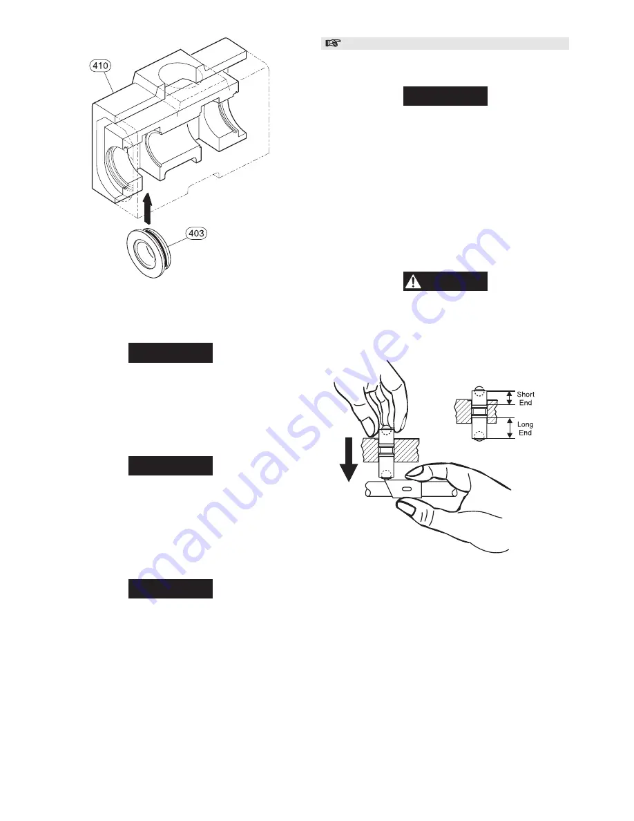
Refer to Dwgs. MHP1408 (Pendant Pilot Operated Valve) or
MHP1407 (Lever Operated Valve) and MHP1411.
NOTICE
• Valve assembly (413) shaft body is longer on one side of
middle groove than the other. Correct placement of valve
assembly is with the longer shaft section located towards the
bottom of the valve body (410). The shorter section will
protrude up, through the valve body.
• To adjust brake release valve ensure sleeve (408) is loose on
shaft (401). If not loose, back off (turn counterclockwise)
setscrew (407).
1.
Rotate sleeve (408) to place the longer edge on top. Refer
to Dwg. MHP1024.
2.
Using gentle hand pressure to prevent damage to the valve
assembly (413), press valve assembly down until ball is in
firm contact with sleeve (408).
CAUTION
• When using sealants care must be taken to use only enough
to effectively do the job. Excess sealant can drip onto internal
components and harden resulting in erratic winch operation
or control problems.
(Dwg. MHP1024)
3.
For units with dual air brakes, repeat step 2 for second
valve assembly (413). On units with a single brake, apply
Loctite
®
609 to pin (412) and press into valve body (410)
[through the air inlet]. Leave 0.16-0.25 inch (4-6.4 mm)
exposed at the top.
4.
Rotate sleeve (408) until long section of sleeve is on the
bottom (180°).
5.
Place washer (417) and spring washer (416) on capscrew
(465) and install in hole located between brake valve
assembly ports in valve body (410). Tighten capscrew and
ensure spring washer locks brake assembly(s) (413) and/or
pin(s) (412) in place.
(Dwg. MHP1023)
12. Secure in place using retainer ring (429). Remove cotter pin
installed in step 8.
NOTICE
• The flats on shaft (401) must be facing the left (or valve)
side of the valve body (410).
13. On opposite side of valve body, slide exhaust poppet (420)
onto shaft (401). Press into valve body.
14. Install spring (422).
15. Slide poppet assembly (423) onto shaft (401).
NOTICE
• Pendant Pilot Valves do not use cotter pin (414). For these
units, use a suitable cotter pin to temporarily contain
components on the shaft. The pin will be removed in a
following step.
16. Align poppet seat with valve body and, using fingers, press
poppet seat into valve body.
17. Secure in place using retainer ring (429).
NOTICE
• Install pin (406) in step 18 only enough to determine
clearance requirements of step 19. Do not fully install pin
until directed.
18. On lever operated control valves install pin (406) in shaft
(401) on the handle end of valve. This is the side of the
valve that the restrictor poppet (402) and restrictor seat
(403) are located. On pendant operated control valves pin
(406) will be installed on both ends of shaft (401).
19. Measure clearance between end of poppet assembly (423)
and pin (406). Using shims (444) attain a clearance of 0.03-
0.05 inch (0.8-1.3 mm) between poppet assembly and pin.
20. When clearance is established, press pin down until pin
protrudes below shaft 0.380 (+/- 0.01) inch (9.7 [+/- 0.3]
mm).
Summary of Contents for ManRider force5 FA5AMR-LAK1
Page 39: ...39 WINCH CROSS SECTION DRAWING ...
Page 40: ...40 WINCH ASSEMBLY PARTS DRAWING ...
Page 42: ...42 MOTOR ASSEMBLY PARTS DRAWING ...
Page 44: ...44 DISC BRAKE ASSEMBLY PARTS DRAWING ...
Page 48: ...48 LEVER OPERATED CONTROL VALVE ASSEMBLY PARTS DRAWING ...
Page 50: ...50 PENDANT OPERATED PILOT CONTROL VALVE ASSEMBLY PARTS DRAWING ...
Page 52: ...52 REMOTE PENDANT ASSEMBLY PARTS DRAWING ...
Page 54: ...54 SHUTTLE VALVE ASSEMBLY PARTS DRAWING ...
Page 56: ...56 EMERGENCY STOP AND OVERLOAD ASSEMBLY PARTS DRAWING ...
Page 64: ...64 SERVICE NOTES ...
Page 65: ...65 SERVICE NOTES ...


