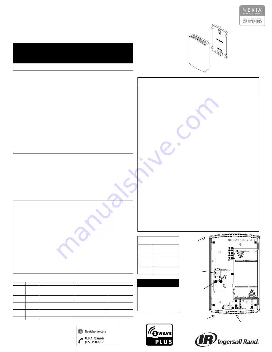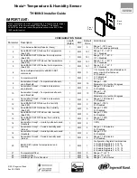
Nexia
TM
Temperature & Humidity Sensor
TH100NX Installer Guide
Tab
ASSOCIATION GROUP INFORMATION TABLE
Group
Profile
Command Classes
Group Name
Max Devices
1
Lifeline
Battery Report, Multilevel
Sensor Report, Device
Reset Locally Notification
Lifeline
1
2
Sensor
Multilevel Sensor Report
Temperature Reports
5
3
Sensor
Multilevel Sensor Report
Humidity Reports
5
4
Sensor
Basic Set
Temperature Driven
Basic Sets
5
5
Sensor
Basic Set
Humidity Driven Basic
Sets
5
6
Sensor
Battery Report
Battery Reports
5
This device complies with Part 15 of the FCC Rules. Operation is subject to the
following two conditions: (1) This device may not cause harmful interference, and
(2) This device must accept any interference received, including interference that
may cause undesired operation.
This equipment has been tested and found to comply with the limits for Class B
Digital Device, pursuant to Part 15 of the FCC Rules. These limits are designed to
provide reasonable protection against harmful interference in a residential
installation. This equipment generates and can radiate radio frequency energy
and, if not installed and used in accordance with the instructions, may cause
harmful interference to radio communications. However, there is no guarantee that
interference will not occur in a particular installation. If this equipment does cause
harmful interference to radio or television reception, which can be determined by
turning the equipment off and on, the user is encouraged to try to correct the
interference by one or more of the following measures.
Reorient or relocate the receiving antenna
Increase the separation between the equipment and receiver
Connect the equipment into an outlet on a circuit different from that to which
the receiver is connected
Consult the dealer or an experienced radio/TV technician for help
Any changes or modifications not expressly approved by the party responsible for
compliance could void the user’s authority to operate the equipment.
This device complies with Industry Canada license-exempt RSS standard(s).
Operation is subject to the following two conditions: (1) this device may not cause
interference, and (2) this device must accept any interference, including
interference that may cause undesired operation of the device.
Le présent appareil est conforme aux CNR d'Industrie Canada applicables aux
appareils radio exempts de licence. L'exploitation est autorisée aux deux
conditions suivantes : (1) l'appareil ne doit pas produire de brouillage, et (2)
l'utilisateur de l'appareil doit accepter tout brouillage radioélectrique subi, même si
le brouillage est susceptible d'encompromettre le fonctionnement.
INSTALL BUTTON
– OVERVIEW
Press once to add or remove the sensor from a Z-Wave Network.
Press and hold for 10 seconds to restore factory defaults.
Press three times rapidly to send a
“BATTERY_REPORT” and
“WAKE_UP_NOTIFICATION” (if installed on a network). The sensor will
stay awake for 30 seconds.
STATUS LED, following a button press:
LED stays on for 30 seconds.
Continuous On: Device is enrolled on a Z-Wave Network.
Continuous Slow Blinking: Device is not enrolled on a Z-Wave Network.
Fast Blinking: Successfully added/removed into/from Z-Wave network.
ADD
– adding the sensor to an existing Z-Wave network
1.
Set your home’s Z-Wave Bridge into ADD Mode.
2.
Press and release the
INSTALL
button on the sensor.
3.
The Status LED will blink rapidly for 3 seconds when it has been added to
your Z-Wave network. Your bridge will also indicate that the sensor was
successfully added.
REMOVE
– removing the sensor from a Z-Wave network
1.
Set your
home’s Z-Wave Bridge into REMOVE Mode.
2.
Press and release the
INSTALL
button on the sensor.
3.
The Status LED will blink rapidly for 3 seconds when it has been removed
from your Z-Wave network. Your bridge will also indicate that the sensor was
successfully removed.
Troubleshooting
: If the sensor fails to add to the network, add a Z-Wave
repeating device (e.g. light module/dimmer) at a location between the bridge and
sensor. First add the repeater to the network following that device’s instructions.
Then try to add the sensor to the network again.
Z-WAVE INSTALLATION
FCC Statement
SPECIFICATIONS
Size
(inches)
3.25 x 2.0 x 0.60
Weight
.25 lbs.
Power
2 x AAA Alkaline
Batteries
RF
Z-Wave ZM5202,
US 908.4 MHz
1.
Remove the back plate by inserting a small screwdriver beneath the tab at
the bottom of the back plate and unsnap it from the front.
2.
Install two AAA batteries (included).
3.
Determine the physical location of the sensor, FOR INDOOR USE ONLY.
a.
For wall mounting, use the provided anchors and screws to mount
the back plate.
4.
Adding to a Nexia Z-Wave Network (Non-Nexia Networks see the Z-Wave
Installation section below)
a.
Use the “Add Device” button on the Nexia portal or mobile app to
start the inclusion process.
b.
When prompted, press the
INSTALL
button on the sensor
c.
Observe enrollment updates and success indication on the Nexia
portal or mobile
app, additionally the sensor’s Status LED will blink
rapidly for 3 seconds.
5.
Snap the sensor onto the back plate keeping the text in the same orientation
as the text on the back plate.
6.
Use your Nexia account to confirm the sensor is listed on the device list.
INSTALLATION
SUMMARY OF OPERATION
Install
Button
© 2017 Ingersoll Rand
Rev. 20170629
These instructions are ONLY for connecting a Z-Wave wireless temper-
ature sensor to a new or existing Z-Wave network. This sensor
CANNOT be used as a remote temperature sensor for an 824, 850 or
1050 comfort control.
IMPORTANT:
FACTORY RESET
Factory Reset should
only be used when the
primary controller is
missing or otherwise
inoperable.
Front
Plate
Back
Plate
Status
LED
ton
Tab
BOTTOM
TOP


