4IRI8N - 4IRI8T ENGINE
Operating & Maintenance Manual
81
Ingersoll-Rand Protec™ Engine Fluid Part
No. 54480918 (1 gallon).
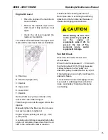
Important: Do not overfill the oil pan with
engine oil. Be sure to keep the specified level
between upper and lower limit on the
dipstick.
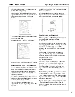
The location depends on the engine installed
on the machine unit.
(A) Dipstick (B) Oil Pan (C) Drain Plug
(A) Engine Oil Filter (B) Loosen (C) Tighten
Draining Water from Filter/Separator
The fuel filter/separator is provided to allow
water to be drained from the fuel system.
Water is heavier than fuel so any water
contained in the system will collect in the
bottom of the bowl.
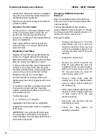
The clear bowl “D” should be checked on a
daily basis and if water is present, it should
be drained from the separator.
Place a suitable container under the
separator to prevent any spillage inside the
machine.
Slacken the drain valve “E” until water drains
from the vent tube.
When all the water has been evacuated,
tighten the drain valve “E” and follow the “fuel
system air bleeding” procedure below.
Fuel System Air Bleeding
The entry of air into the fuel system will cause
difficult engine starting or engine
malfunction.
When carrying out service procedures such
as emptying the fuel tank, draining the filter/
separator, and changing the fuel filter
element be sure to bleed air from the fuel
system.
To activate the “automatic air-bleeding
system”, turn the key switch to the “ON”
position and energize the electromagnetic
pump to bleed the air.
Air Bleeding Method:
When the “starter switch” is set to the “ON”
position to activate the electromagnetic
pump, fuel is forced to the fuel valve of each
injector nozzle, so that any air in the fuel
system bleeds off automatically to the fuel
tank.
Note: Although the fuel system can bleed air
automatically when the key switch is in the
“ON" position, air can also be manually bled
by use of the primer pump facility in the filter/
separator assembly.
By unscrewing the plastic primer pump head
`A' and stroking it up and down, any air
bubbles in the system will be purged back to
the fuel tank.
Summary of Contents for P185AWIR
Page 6: ...1 4...
Page 7: ...3 FOREWORD...
Page 8: ...4...
Page 10: ...6...
Page 11: ...7 DRAWBAR NOTICE...
Page 12: ...Operating Maintenance Manual 8...
Page 14: ...Operating Maintenance Manual 10...
Page 15: ...11 Section 1 Safety...
Page 19: ...Safety Operating Maintenance Manual 15...
Page 20: ...Operating Maintenance Manual Safety 16...
Page 22: ...Operating Maintenance Manual Safety 18...
Page 23: ...Safety Operating Maintenance Manual 19...
Page 25: ...21 Section 2 WARRANTY...
Page 30: ...Operating Maintenance Manual WARRANTY 26...
Page 32: ...Operating Maintenance Manual WARRANTY 28...
Page 33: ...29 Section 3 NOISE EMISSION...
Page 39: ...35 Section 4 GENERAL DATA...
Page 42: ...Operating Maintenance Manual GENERAL DATA 38...
Page 43: ...39 SECTION 5 OPERATION...
Page 51: ...47 Section 6 MAINTENANCE...
Page 59: ...55 Section 7 LUBRICATION...
Page 61: ...57 Section 8 Trouble Shooting...

