background image

NOISE EMISSION

Operating & Maintenance Manual

22478341 (1-15-07) Rev A 

23

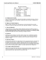
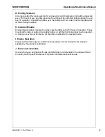
G. Cooling Systems

All components of the cooling system for engine water and compressor oil should be inspected 
every 250 hours of use. Any discrepancies found should be corrected before placing the unit 
back in operation. Unrestricted airflow over the radiator and oil cooler must be maintained at 
all times during operation.

H. Isolation Mounts

Engine/airend isolation mounts should be inspected after each 250 hours of operation. Those 
mounts with cracks or splits in the molded rubber, or with bent or broken bolts due to operation 
or storage in severe environments, all should be replaced with equivalent parts.

I. Engine Operation

Inspect and maintain engine condition and operation as recommended in the manuals 
supplied by the engine manufacturer.

J. Fuels and Lubricants

Use only the types and grades of fuels and lubricants recommended in the Ingersoll Rand 
Company and Engine Manufacturer’s Operator and Maintenance Manuals.

Summary of Contents for P250WJD

Page 1: ...22478341 01 15 07 Rev A P250WJD Code C Doosan purchased Bobcat Company from Ingersoll Rand Company in 2007 Any reference to Ingersoll Rand Company or use of trademarks service marks logos or other proprietary identifying marks belonging to Ingersoll Rand Company in this manual is historical or nominative in nature and is not meant to suggest a current affiliation between Ingersoll Rand Company and...

Page 2: ...CALIFORNIA Proposition 65 Warning Diesel engine exhaust and some of its constituents are known to the State of California to cause cancer birth defects and other reproductive harm ...

Page 3: ...tion pertains only to machines distributed within the United States 3 20 Noise Emission Control Maintenance Log 3 21 Noise Emission Warranty 3 21 Introduction 3 21 GENERAL DATA 4 25 General Data 4 26 Models 4 26 Compressor 4 26 Engine Diesel 4 26 Fluid Capacities 4 26 Units Measurements Weights 4 26 Running Gear 4 26 Expendable Service Parts 4 27 OPERATION 5 29 Before Towing 5 30 ...

Page 4: ...attery 6 39 Fasteners 6 39 Radiator 6 40 Hoses 6 40 Compressor Oil Cooler 6 41 Compressor Oil 6 41 Receiver Separator Systems 6 41 Scavenge Line 6 42 Exterior Finish Care 6 42 MAINTENANCE SCHEDULE 6 44 LUBRICATION 7 45 Lubrication 7 46 Portable Compressor Fluid Chart 7 46 TROUBLE SHOOTING 8 47 Trouble Shooting 8 48 Introduction 8 48 Action Plan 8 48 Trouble Shooting Chart 8 49 ...

Page 5: ...22478341 1 15 07 Rev A 3 FOREWORD ...

Page 6: ...turer and wherever possible be of a type approved by Ingersoll Rand clearly rated for a pressure at least equal to the machine maximum allowable working pressure compatible with the compressor lubricant coolant accompanied with instructions for safe installation operation and maintenance Details of approved equipment are available from Ingersoll Rand Service departments The use of repair parts oth...

Page 7: ... the reliability of the machine The purpose of this manual is to train the operator with functions operation and basic service and maintenance requirements of the compressor During the preparation of this manual every effort was made to ensure the adequacy and accuracy of the contents Your Ingersoll Rand dealer will assist with setup and initial startup of the compressor He will also provide brief...

Page 8: ...6 22478341 1 15 07 Rev A Always use Ingersoll Rand Replacement parts ...

Page 9: ...22478341 1 15 07 Rev A 7 DRAWBAR NOTICE ...

Page 10: ... 1 Remove hardware box from compressor toolbox 2 Open box and remove the bag containing hardware safety chains and assembly instructions 3 Using the jack raise the front of the unit so that the legs are approximately 1 inch above the ground 4 Remove the temporary retaining bolts from both sides of the frame at the drawbar connection See Fig 1 5 Carefully lower drawbar to the Level Position 6 Insta...

Page 11: ...22478341 1 15 07 Rev A 9 SAFETY ...

Page 12: ...nstalled in or connected to the machine must have safe working pressure ratings of at least the machine safety valve rating If more than one compressor is connected to one common downstream plant effective check valves and isolation valves must be fitted and controlled by work procedures so that one machine cannot accidentally be pressurized or over pressurized by another Compressed air must not b...

Page 13: ...Disconnected air hoses whip and can cause serious injury or death Always attach a safety flow restrictor to each hose at the source of supply or branch line in accordance with OSHA Regulation 29CFR Section 1926 302 b Rotating fan blade can cause serious injury Do not operate without guard in place Use care to avoid contacting hot surfaces engine exhaust manifold and piping air receiver and air dis...

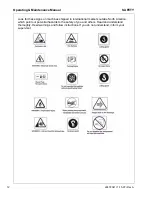
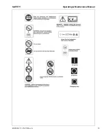
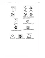
Page 14: ...k for these signs on machines shipped to international markets outside North America which point out potential hazards to the safety of you and others Read and understand thoroughly Heed warnings and follow instructions If you do not understand inform your supervisor ...

Page 15: ...SAFETY Operating Maintenance Manual 22478341 1 15 07 Rev A 13 ...

Page 16: ...Operating Maintenance Manual SAFETY 14 22478341 1 15 07 Rev A ...

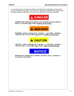
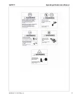
Page 17: ...visor DANGER DANGER Red Background indicates an imminently hazardous situation which if not avoided will result in death or serious injury WARNING WARNING Orange Background indicates a potentially hazardous situation which if not avoided could result in death or serious injury CAUTION CAUTION Yellow Background indicates a potentially hazardous situation which if not avoided may result in minor or ...

Page 18: ...Operating Maintenance Manual SAFETY 16 22478341 1 15 07 Rev A ...

Page 19: ...SAFETY Operating Maintenance Manual 22478341 1 15 07 Rev A 17 ...

Page 20: ...eading DANGER WARNING or CAUTION Decal part numbers are on the bottom of each decal and are also listed in the compressor s parts manual Submit orders for Safety Decals to the Mocksville Parts Service Department The no charge order should contain only Safety Decals Help promote safety Assure that decals are present on the machines Replace decals that are not readable ...

Page 21: ...22478341 1 15 07 Rev A 19 NOISE EMISSION ...

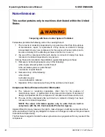
Page 22: ...m or parts thereof b the air intake system or parts thereof c enclosure or parts thereof 4 Removal of any of the following a fan shroud b vibration mounts c sound absorption material 5 Operation of the compressor with any of the enclosure doors open Compressor Noise Emission Control Information A The removal or rendering inoperative other than for the purpose of maintenance repair or replacement o...

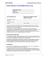
Page 23: ...r part component or system of the air compressor Defects in the design assembly or in any part component or system of the compressor which at the time of sale to the first retail purchaser caused noise emissions to exceed Federal Standards are covered by this warranty for the life of the air compressor Introduction The unit for which this Maintenance Log is provided conforms to U S E P A Regulatio...

Page 24: ...should be retightened repaired or if missing replaced immediately to prevent subsequent damage and noise emission increase E Enclosure Panels Enclosure panels should also be inspected at 100 hour operational intervals All panels that are warped punctured torn or otherwise deformed such that their noise containment function is reduced should be repaired or replaced before the next operation interva...

Page 25: ...Isolation Mounts Engine airend isolation mounts should be inspected after each 250 hours of operation Those mounts with cracks or splits in the molded rubber or with bent or broken bolts due to operation or storage in severe environments all should be replaced with equivalent parts I Engine Operation Inspect and maintain engine condition and operation as recommended in the manuals supplied by the ...

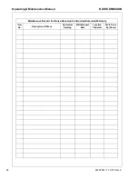
Page 26: ...ce Manual NOISE EMISSION 24 22478341 1 15 07 Rev A Maintenance Record For Noise Emission Control And Extended Warranty Item No Description Of Work Hourmeter Reading Maint inspect Date Location City state Work Done By Name ...

Page 27: ...22478341 1 15 07 Rev A 25 GENERAL DATA ...

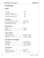
Page 28: ...ities Compressor Lubricant 12 quarts 11 4 litres Engine Crankcase Lubricant 10 8 quarts 10 2 litres Fuel Tank 29 U S gal 110 litres Units Measurements Weights Overall Length 11 5 3 5 meters Overall Height 4 8 feet 1 46 meters Overall Width 5 7 feet 1 74 meters Track Width 4 9 feet 1 49 meters Running Gear Tire Size P215 75RX15 Inflation Pressure cold 35 psi Towing Speed maximum 65 mph 105 km hr Un...

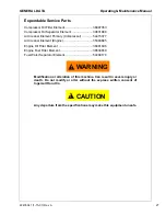
Page 29: ...pressor 54415377 Air Cleaner Element Engine 35393685 Engine Oil Filter Element 36881696 Engine Fuel Filter Element 36534659 Fuel Water Separator Element 54468178 WARNING Modification or alteration of this machine Can result in severe injury or death Do not modify or alter without the express written consent of Ingersoll Rand Co CAUTION Any departure from the specifications may make this equipment ...

Page 30: ...28 22478341 1 15 07 Rev A Always use Ingersoll Rand Replacement parts ...

Page 31: ...22478341 1 15 07 Rev A 29 OPERATION ...

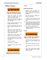
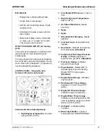
Page 32: ... equipped Test lights running stop and turn signals WARNING Always raise or remove jack for maximum ground clearance before towing Setting Up All Units Position as level as possible The design of these units permits a 15 degree sidewise limit on out of level operation When the unit is to be operated out of level it is important 1 To keep the engine crankcase oil level near the high level mark with...

Page 33: ...erature Coolant above 220 F 104 C 2 Low Engine Oil Pressure 12 psi or less 3 High Compressor Temperature 248 F 120 C 4 Air Filters Restricted Needs servicing 5 Spare 6 Spare 7 Alternator Not Charging Needs attention 8 Low Fuel Level Must add fuel to operate 9 Hourmeter Records running time for maintenance Standard 10 Compressor Discharge Pressure Gauge Indicates pressure in receiver tank psi kPa S...

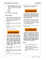
Page 34: ... marks on dipstick Check the fuel level Add only CLEAN DIESEL fuel for maximum service from the engine Check the compressor lubricating fluid level between bottom and midway of the sight glass on the separator tank WARNING This machine produces loud noise with doors open Extended exposure to loud noise can cause hearing loss Wear hearing protection when doors or valve s are open Close all doors to...

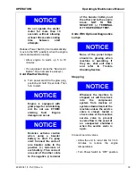
Page 35: ...tart To jump start Connect the ends of one booster cable to the positive terminals of each battery Then connect one end of the other cable to the negative terminal of the booster battery and the other end to the engine block NOT TO THE NEGATIVE TERMINAL OF THE WEAK BATTERY Units With Optional Diagnostics Lamps NOTICE None of the panel lamps should be glowing when machine is operating If they are s...

Page 36: ...he service valve will slowly bleed air from the hose Do not disconnect hoses until all pressure has been vented NOTICE Do NOT wire around or bypass a shutdown sensor or switch Machine has shutdown and sensors as follows Low Engine oil pressure in the engine High engine coolant temperature in the engine Compressor Air Oil Temperature At the airend outlet In separator tank UNITS WITH DIAGNOSTIC LAMP...

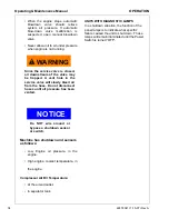
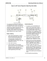
Page 37: ... jam nut on air actuating cylinder A and then turn cylinder rod D until throttle arm G is forced against the governor stop After Starting Unit 4 If equipped push the SERVICE AIR button on the control panel making certain the button does not pop back out The unit should speed up and then unload and drop back to IDLE With the unit unloaded turn the adjusting screw on the pressure regulator clockwise...

Page 38: ...36 22478341 1 15 07 Rev A Always use Ingersoll Rand Replacement parts ...
Page 39: ...22478341 1 15 07 Rev A 37 MAINTENANCE ...

Page 40: ...eventive maintenance is the easiest and the least expensive type of maintenance Maintaining your unit and keeping it clean at all times will facilitate servicing Scheduled Maintenance The maintenance schedule is based on normal operation of the unit This page can be reproduced and used as a checklist by the service personnel In the event unusual environmental operating conditions exist the schedul...

Page 41: ... and test any diagnostic lamps prior to start up During operation observe the gauges and any lamps for proper functioning Refer to Operating Controls for the normal readings Fuel Tank CLEAN fuel in the fuel tanks is vitally important and every precaution should be taken to ensure that only clean fuel is poured or pumped into the tank When filling the fuel tank on this unit by methods other than a ...

Page 42: ...ollows Pulling on the tubing will cause the inner sleeve to withdraw and compress thus tightening the connection The tubing can be withdrawn only while holding the sleeve against the fitting The tubing can be removed and replaced numerous times without losing its sealing ability To install the nylon tubing make a mark with tape or grease pencil approximately 7 8 inch from the end of the tubing Ins...

Page 43: ...of grease oil and dirt from the exterior surfaces of the oil cooler core so that the entire cooling area can transmit the heat of the lubricating and cooling oil to air stream In the event foreign deposits such as sludge and lacquer accumulate in the oil cooler to the extent that its cooling efficiency is impaired a resulting high discharge air temperature is likely to occur causing shut down of t...

Page 44: ... in this section 2 Thoroughly clean scavenge line any orifice and check valve 3 Assure minimum pressure valve orifice is operational 4 Run unit at rated operating pressure for 30 to 40 minutes to permit element to clear itself Exterior Finish Care This unit was painted and heat cured at the factory with a high quality thermoset polyester powder coating The following care will ensure the longest po...

Page 45: ...essure pot and use about 2 5 pounds of air pressure This will allow the primer to splatter causing the textured look NOTE You must be careful not to put too much primer on at one time this will effect the amount of texture that you are trying to achieve Allow the texture coat to flash for 20 minutes or until dry to touch 10 Apply any of Duponts Topcoat Finishes such as Imron or Centari according t...

Page 46: ...leaner PreCleaner Dumps C Fan Alternator Belts C Battery Connections Electrolyte C Tire Pressure and Surface C Wheel Lug Nuts C Hoses oil air intake etc C Automatic Shutdown System Test C Air Cleaner System Visual C Compressor Oil Cooler Exterior C CLEAN Engine Radiator Exterior C CLEAN Fasteners Guards C Air Cleaner Elements R Fuel Water Separator Element R Compressor Oil Filter Element R Compres...

Page 47: ...22478341 1 15 07 Rev A 45 LUBRICATION ...

Page 48: ...nty section for details or contact your IR representative Design Operating Pressure Ambient Temperature Specification 100 psi to 300 psi 100F to 1250F 230 C to 520 C Preferred IR Pro Tec Alternate ISO Viscosity Grade 46 with rust and oxidation inhibitors designed for air compressor service 350 psi 230 C to 520 C 100 F to 1250 F 650 F to 1250 F 18 C to 52 C Preferred IR XHP 605 Alternate IR XHP405 ...

Page 49: ...22478341 1 15 07 Rev A 47 TROUBLE SHOOTING ...

Page 50: ... been done 4 If the compressor will still operate is it safe to continue operating it to make further checks B Do the Simplest Things First Most troubles are simple and easily corrected For example most complaints are low capacity which may be caused by too low an engine speed or compressor over heats which may be caused by low oil level Always check the easiest and most obvious things first follo...

Page 51: ...own Fuse Replace fuse Check for Short 10 Volts at Shutdown Solenoid Check battery and alternator Make repairs Engine Malfunctioning See Trouble Shooting in Engine Section Airend Malfunctioning See Table 10 Cause Corrective Action Out of Fuel Add CLEAN diesel Fuel Clogged Fuel Filters Service filters Compressor Oil Level Too Low Add corrected oil Loose Wire Connection Repair or replace connection L...

Page 52: ...o cleaner environment Out of Level 15 degrees Relocate or reposition unit Ambient Temp 125 F 52 C Above spec limit Loose Wire Connection Repair or replace Broken Engine Fan Belt Replace fan belt set Malfunctioning Circuit Board Replace circuit board Complaint Corrective Action Low Oil Level Add oil Clogged Oil Filter Element s Replace element s Out of Level 15 degrees Relocate or reposition Loose ...

Page 53: ...gine Oil Pressure Switch Pull wire off Replace switch Defective Shutdown Solenoid Carefully block air inlet to stop engine Malfunctioning Relay Replace relay Defective Start Switch Pull wire off shutdown solenoid Replace defective item Wire Shorted Hot Repair short Complaint Corrective Action Dirty Cooler Clean exterior surfaces Low Oil Level Add oil Look for any leaks Clogged Oil Filter Elements ...

Page 54: ...s fuel Engine idle speed too low Raise No Load speed Rubber Mounts Loose or Damaged Tighten or replace Anti rumble valve not working Repair or Replace Drive Coupling Defective Replace coupling Defective Fan Replace fan Engine Malfunctioning See Trouble Shooting in Engine Section Airend Malfunctioning See Table 15 and 17 Complaint Corrective Action Engine RPM too Low Adjust RPM Malfunctioning Air C...

Page 55: ... Oil Line s Remove clean and replace line s Replace seal Malfunctioning Seal Consult dealer Replace seal Scored Shaft See instructions in new seal kit Complaint Corrective Action Incorrect Pressure Regulator Adjustment Adjust regulator Leak in Regulator Piping Find and repair leak s Malfunctioning Pressure Regulator Replace regulator Malfunctioning Inlet Valve Unloader Inspect valve Repair Replace...

Page 56: ...54 22478341 1 15 07 Rev A Always use Ingersoll Rand Replacement parts ...
Page 57: ... 2007 Ingersoll Rand Company Printed in the USA Ingersoll Rand Company P O Box 868 501 Sanford Ave Mocksville N C 27028 ...

Reviews: