04576070_ed2
5
Maintenance
WARNING
Always wear eye protection when operating or performing maintenance on this tool.
Always turn off the air supply and disconnect the air supply hose before installing, removing or adjusting any accessory on this tool or
before performing any maintenance on this tool.
Whenever one of the Sanders is disassembled for overhaul or
replacement of parts, lubricate as follows:
Always wipe the Vanes (21) with a light film of oil before inserting
them into the vane slots.
•
Inject 0.5 to 1.0 cc of
Ingersoll Rand No.10
Oil into the air Inlet
Bushing (1) after assembly.
•
Disassembly
Lubrication
General Instructions
1. Do not disassemble the tool any further than necessary to replace
or repair damaged parts.
2. Do not press any needle bearing from a part unless you have a
new needle bearing on hand for installation. Needle bearings are
always damaged during the removal process.
3. When grasping a tool or part in a vise, always use leather–covered
or copper–covered vise jaws to protect the surface of the part
or tool and help prevent distortion. This is particularly true of
threaded members and housings.
4. Do not remove any part which is a press fit in or on a
subassembly unless the removal of that part is necessary for
repairs or replacement.
Removal of the Sanding Pad
1. Place a 1/8” hex wrench in the set screw in the center of the
Pad (27).
2. Holding the set screw in place, unscrew the Pad from the set
screw.
3. Remove the spacer from the set screw.
4. With the Pad removed, lubricate the counterbalance needle
bearing by injecting one or two strokes of
Ingersoll Rand No. 68
Grease into the threaded end of the Spindle.
Disassembly of the Base Adapter
1. Remove the Cold Air Channel from the tool by removing the
Spring Clamp (33).
2. Remove the Shroud to expose two Roll Pins (41).
3. Using pliers or a vise, remove the Roll Pins.
4. The Housing Adapter (32) will slip out of the Sander face,
exposing the Motor Lock Ring (24).
Disassembly of the Spindle
1. Remove the Sanding Pad and Base Adapter.
2. Remove the Retaining Ring (26).
3. Remove the Spindle Assembly (25) including bearing.
NOTICE
Do not attempt to remove the bearing from the Spindle.
4. Remove the Motor Lock Ring (22) and pull the motor and
Seal (17) from the Housing (1).
5. Remove the Retaining Ring (13).
6. Using special brass blocks to fit around the outside diameter of
the Cylinder (16), clamp around the Cylinder and press the shaft
of the Counterbalance (24) through the Bearing (14) and Rear End
Plate (15).
7. Remove the Vanes (19), Rotor (18) and Key (23).
8. Remove the Front End Plate (20) and Bearing (14).
Disassembly of the Throttle
1. Remove the Inlet Adapter (9). This will release the Spring (8) and
Tip Valve (7).
NOTICE
Do not remove the Seat (6) unless it has been damaged.
2. Remove the Muffler (11), releasing the Muffler Tube (10).
3. To remove the Valve Stem (2), remove the Roll Pin (4) and
Lever (3).
Assembly
General Instructions
1. Always press on the
inner
ring of a ball–type bearing when
installing the bearing on a shaft.
2. Always press on the
outer
ring of a ball–type bearing when
pressing the bearing into a bearing recess.
3. Whenever grasping a tool or part in a vise, always use
leather–covered or copper–covered vise jaws. Take extra care not
to damage threads or distort housings.
4. Except for bearings, always clean every part and wipe every part
with a thin film of oil before installation.
5. Check every bearing for roughness. If an open bearing must be
cleaned, wash it thoroughly in clean solution and dry with a clean
cloth. Sealed or shielded bearings should not be cleaned. Work
grease into every open bearing before installation.
6. Apply a film of O-ring lubricant to every O-ring before installation.
7. Unless otherwise noted, always press on the stamped end of a
needle bearing when installing a needle bearing into a recess.
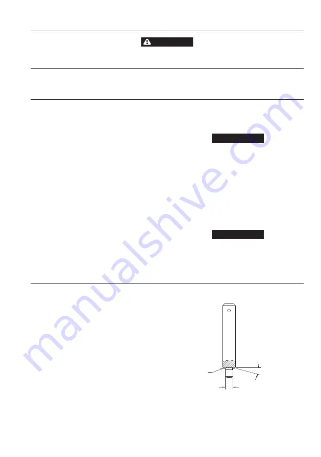
Use a bearing inserting tool similar to the one shown in
Dwg. TPD786.
Needle Bearing inserting Tool
Shoulder to
Regulate Depth
Pilot to fit I.D. of Bearing.
Length of Pilot to be
approximately 1/8” less than
length of Bearing
15°
Dwg. TPD-786.


