2
Safety First
Compressed air and electricity can be dangerous. Before undertaking any work on the compressor,
ensure that the electrical supply has been isolated and the compressor has been relieved of all
pressure. Use proper
L
ock
O
ut
T
ag
O
ut procedures to ensure you and your coworkers safety.
Keep all parts of the body and any hand-held tools or other conductive objects, away from exposed
live parts of the compressor electrical system. Maintain dry footing, stand on insulating surfaces and
do not contact any other portion of the compressor when making adjustments or repairs to exposed
live parts of the compressor electrical system. Close and lock all access doors when the compressor
is left unattended.
Do not use extinguishers intended for Class A or Class B fires on electrical fires. Use only
extinguishers suitable for class
BC
or class
ABC
fires. Attempt repairs only in clean, dry, well lighted
and ventilated areas. Connect the compressor only to electrical systems that are compatible with its
electrical characteristics and that are within it’s rated capacity.
WARNING
Imposing a normal or emergency stop on the compressor will only relieve pressure upstream
of the minimum pressure valve on top of the separator tank. If maintenance work is required
downstream of this valve, ensure that all pressure is relieved at the process vent point
external to the compressor This state is advised by selecting PACKAGE DISCHARGE
PRESSURE on the control panel.
Summary of Contents for R110IU-10
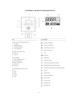
Page 5: ...5 S3 Intellisys Controller Operating Instructions...
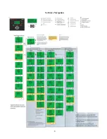
Page 6: ...6 Software Navigation...
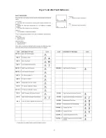
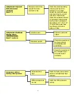
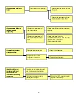
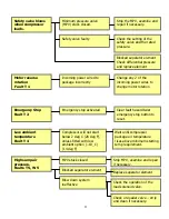
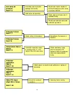
Page 7: ...7 Eiger Controller Fault Indicators 020 Tr Motor PTC Open High Motor Temperature...
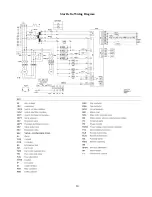
Page 14: ...14 Star Delta Wiring Diagram...
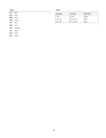
Page 15: ...15...
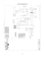
Page 16: ...16 Soft Start Wiring Diagram...
Page 17: ...17...
Page 18: ...18 Line Start Schematic...
Page 19: ...19...
Page 20: ...20 Process and Instrumentation Diagram...
Page 21: ...21...
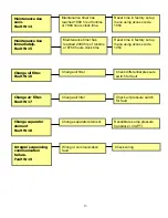
Page 28: ...28 Maintenance...
Page 29: ...29 Maintenance...
Page 30: ...30 Maintenance...
Page 31: ...31 S3 Controller Input Output Overview AI Analog Input DI Digital Input DO Digital Output...
Page 45: ...45 Standard S3 Menu Structure and Parameters Table 12...
Page 46: ...46 Standard S3 Menu Structure and Parameters Table 12...
Page 47: ...47 Standard S3 Menu Structure and Parameters Table 12...
Page 49: ...49 Modbus Register Listing...
Page 50: ...50 Table 13 Modbus Register Listing...
Page 52: ...52 Appendix 1 Thermistor 2ATT 34 to 124 C 255 F Air end Discharge...
Page 53: ...53...
Page 54: ...54...
Page 55: ...55...
Page 56: ...56...
Page 57: ...57...
Page 58: ...58 General Specifications for Eiger Packages...
Page 59: ...59...
Page 60: ...60...
Page 61: ...61...
Page 62: ...62...
Page 63: ...63...
Page 64: ...64...
Page 65: ...65...
Page 66: ...66...
Page 67: ...67...
Page 68: ...68...
Page 69: ...69...
Page 70: ...70...
Page 71: ...71...
Page 72: ...72...
Page 73: ...73...
Page 74: ...74...
Page 75: ...75...
Page 76: ...76...
Page 77: ...77...
Page 78: ...78...
Page 79: ...79...

