22
GENERAL OVERVIEW OF THE COMPRESSOR
The compressor is an electric motor driven, single stage screw compressor, complete with
accessories piped, wired and base plate mounted. It is a totally self contained air compressor
package. The standard compressor is designed to operate in an ambient range of 2_C to 46_C (35_F
to 115_F). The standard maximum temperature of 46_C (115_F) is applicable up to an elevation of
1000m (3280ft) above sea level. Above this altitude significant reductions in ambient temperature are
required if a standard motor is to be used. Compression in the screw type air compressor is created
by the meshing of two (male & female) helical rotors.
The air/coolant mixture discharges from the compressor into the separation system. This system
removes all but a few PPM of the coolant from the discharge air. The coolant is returned to the
cooling system and the air passes to the after cooler and out of the compressor through the moisture
separator (optional).
Air is pulled into the machine by the cooling fan and is pushed through the combined cooler / after
cooler. By cooling the discharge air and passing it through the separator, much of the water vapor
which is naturally present in the air, can be removed.
The coolant system consists of a sump, cooler, thermostatic valve and a filter. When the unit is
operating, the coolant is pressurized and forced to the compressor bearings. The compressor load
control system is automatic ’On
−
Off line’. This is accomplished by the Intellisys S3 Controller
monitoring the discharge pressure and operating the SV1 solenoid valve. When the load valve is on
(Loading) the blow down solenoid valve SV3 is off and this logic reverses when the unit unloads. The
compressor will operate to maintain a set discharge line pressure and is provided with an auto restart
system for use in plants where the air demand varies widely. Panel instrumentation is provided to
indicate the compressor operating conditions and general status.
CAUTION
LOW DEMAND APPLICATIONS
During periods of low demand, the compressor may not reach its normal operating
temperature. Sustained operation at low demand can result in the build up of condensate in
the coolant. If this situation occurs, the lubricating characteristics of the coolant can be
impaired which may lead to damage of the compressor.
THE COMPRESSOR SHOULD BE ALLOWED AMPLE LOADED RUNNING TIME
.
Summary of Contents for R110IU-10
Page 5: ...5 S3 Intellisys Controller Operating Instructions...
Page 6: ...6 Software Navigation...
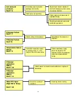
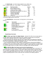
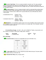
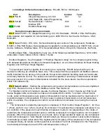
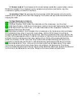
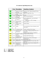
Page 7: ...7 Eiger Controller Fault Indicators 020 Tr Motor PTC Open High Motor Temperature...
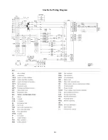
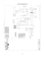
Page 14: ...14 Star Delta Wiring Diagram...
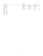
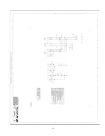
Page 15: ...15...
Page 16: ...16 Soft Start Wiring Diagram...
Page 17: ...17...
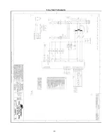
Page 18: ...18 Line Start Schematic...
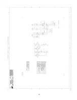
Page 19: ...19...
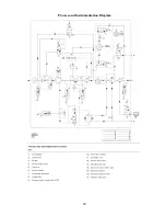
Page 20: ...20 Process and Instrumentation Diagram...
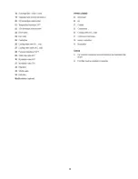
Page 21: ...21...
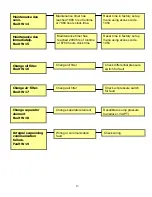
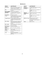
Page 28: ...28 Maintenance...
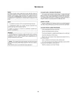
Page 29: ...29 Maintenance...
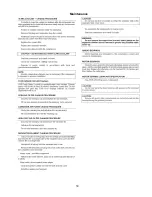
Page 30: ...30 Maintenance...
Page 31: ...31 S3 Controller Input Output Overview AI Analog Input DI Digital Input DO Digital Output...
Page 45: ...45 Standard S3 Menu Structure and Parameters Table 12...
Page 46: ...46 Standard S3 Menu Structure and Parameters Table 12...
Page 47: ...47 Standard S3 Menu Structure and Parameters Table 12...
Page 49: ...49 Modbus Register Listing...
Page 50: ...50 Table 13 Modbus Register Listing...
Page 52: ...52 Appendix 1 Thermistor 2ATT 34 to 124 C 255 F Air end Discharge...
Page 53: ...53...
Page 54: ...54...
Page 55: ...55...
Page 56: ...56...
Page 57: ...57...
Page 58: ...58 General Specifications for Eiger Packages...
Page 59: ...59...
Page 60: ...60...
Page 61: ...61...
Page 62: ...62...
Page 63: ...63...
Page 64: ...64...
Page 65: ...65...
Page 66: ...66...
Page 67: ...67...
Page 68: ...68...
Page 69: ...69...
Page 70: ...70...
Page 71: ...71...
Page 72: ...72...
Page 73: ...73...
Page 74: ...74...
Page 75: ...75...
Page 76: ...76...
Page 77: ...77...
Page 78: ...78...
Page 79: ...79...

