23
Input/Output and Alarm Information for
Intellisys S3 Controller
1.0
Hardware Input / Output Information
Each I/O and software function is labeled as
STD
where the function is available in the standard
controller (
R
apidly
D
eveloping
E
conomies) and
ENH
where the function is available in the enhanced
controller (
RDE
– Options and Developed Markets).
1.1
Analog Inputs
- 10 bit resolution. .5% Full scale accuracy. Pressure Transducer, 2 Wire, 4-
20 ma, Loop Powered.
Sensor Range Description Control Term
STD
4APT 0-232 Psi Package Discharge X05 1-2
ENH
3APT 0-232 Psi Sump, Wet Side X05 5-6
Temperature, 2 Wire, 10 K ohm Thermistor, see appendix 1 for Resistance table!
Sensor Range Description Control Term
STD
2ATT -34 to 124 °C (255 F) Air end Discharge X05 3-4
1.2
Analog Output
- 0-20ma, 24Vdc, max load 500 Ohms, .020ma resolution,
Output Description Control Term
STD
#1 PORO Horn (Using Solid State Relay) X06 1-2
Analog Inputs Comments
STD
Pressure Input Calibration - Initiates an automatic
calibration routine for reading and
correcting the pressure
transducer inputs with a known zero Psi input.
A zero offset calibration should
be performed by first the user verifying the pressure applied to the pressure transducer is in fact 0
PSI. Initiating this calibration routine will read and store a new zero offset value for the analog inputs.
This value is used as an offset for all future pressure readings. The display (UI) should indicate to the
user that a zero Psi reading has been successfully made and stored for the new zero PSI offset value
by displaying a successful message or icon. If when reading the analog input for the 0 PSI value, the
actual reading is greater than +/- 10% of the scale, the calibration will not be performed for that
particular sensor and the previous pressure offset value will be retained. A Sensor Calibration Failure
will be displayed indicating which input has failed and also adding an entry into the Alarm Log. If the
Developed Markets features are enabled, the Sump Pressure transducer will be present and should
be calibrated along with the Package Discharge Pressure transducer. Span calibration is not
accessible by the customer. The calibration is done through the advanced set up menu as shown in
the flow chart on page 6.
Summary of Contents for R110IU-10
Page 5: ...5 S3 Intellisys Controller Operating Instructions...
Page 6: ...6 Software Navigation...
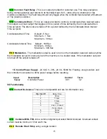
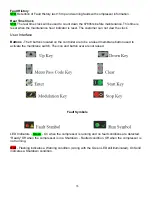
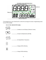
Page 7: ...7 Eiger Controller Fault Indicators 020 Tr Motor PTC Open High Motor Temperature...
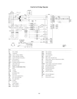
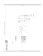
Page 14: ...14 Star Delta Wiring Diagram...
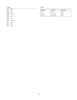
Page 15: ...15...
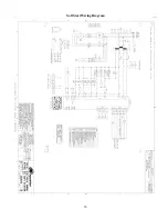
Page 16: ...16 Soft Start Wiring Diagram...
Page 17: ...17...
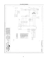
Page 18: ...18 Line Start Schematic...
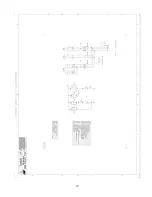
Page 19: ...19...
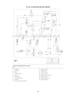
Page 20: ...20 Process and Instrumentation Diagram...
Page 21: ...21...
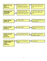
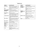
Page 28: ...28 Maintenance...
Page 29: ...29 Maintenance...
Page 30: ...30 Maintenance...
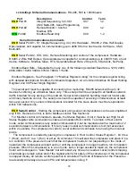
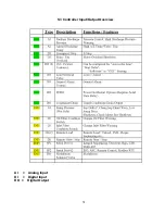
Page 31: ...31 S3 Controller Input Output Overview AI Analog Input DI Digital Input DO Digital Output...
Page 45: ...45 Standard S3 Menu Structure and Parameters Table 12...
Page 46: ...46 Standard S3 Menu Structure and Parameters Table 12...
Page 47: ...47 Standard S3 Menu Structure and Parameters Table 12...
Page 49: ...49 Modbus Register Listing...
Page 50: ...50 Table 13 Modbus Register Listing...
Page 52: ...52 Appendix 1 Thermistor 2ATT 34 to 124 C 255 F Air end Discharge...
Page 53: ...53...
Page 54: ...54...
Page 55: ...55...
Page 56: ...56...
Page 57: ...57...
Page 58: ...58 General Specifications for Eiger Packages...
Page 59: ...59...
Page 60: ...60...
Page 61: ...61...
Page 62: ...62...
Page 63: ...63...
Page 64: ...64...
Page 65: ...65...
Page 66: ...66...
Page 67: ...67...
Page 68: ...68...
Page 69: ...69...
Page 70: ...70...
Page 71: ...71...
Page 72: ...72...
Page 73: ...73...
Page 74: ...74...
Page 75: ...75...
Page 76: ...76...
Page 77: ...77...
Page 78: ...78...
Page 79: ...79...

