26
1.6
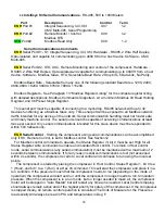
Intellisys
S3
Serial Communications
- RS-485, 500 to 1000 Meters
Port Description Control Term
ENH
Port #1 Integral Sequencing, X4I, X8I X07 1-2
CMC Multi-485, Serial Programming
ENH
Port #2 Remote Monitor / Control, X08 1-2
Modbus RTU
STD
Port#2 Modbus Read Only X08 1-2
Serial Communications Comments
ENH
Serial Port #1 - S1 Integral Sequencing, X4I, X8I, Hardware - RS485, 2 Wire Half Duplex,
Opto-isolated, and capable for communicating up to 4000 ft from a host device. Software - CMC
Multi-485.
ENH
Serial Port #2 - IEO, ASC, Remote Monitoring and control of the compressor. Hardware -
RS485, 2 Wire Half Duplex, Opto-isolated,and capable for communicating up to 4000 ft from a host
device. Software - Modbus Slave, RTU, Selectable Baud Rate, 2 Stop bits, 8 Data bits, No Parity.
Modbus Baud Rate - Selectable from any one of the following standard Baud rates. 1200, 2400,
4800,9600, 19200, 38400, 57600, 76800, 115200.
Modbus Registers - See Paragraph 13 “Modbus Register Listing” for the compete register listing
with detailed descriptions. Modbus Commands Supported - At a minimum Modbus 03 Read Holding
Register, and 06 Preset Single Register.
This serial port must be capable of connecting to a multi-drop, RS485 network with up to 32
devices functioning as a Modbus Slave only. This serial port will be exposed to all Modbus network
traffic intended for any device on the network. Serial communication handling must not hinder safe
and timely machine control. The serial port should be capable of servicing communications at least
twice per second. Any serial communications intended for this slave device must be responded to
within 500 milliseconds.
ENH
Serial Control
- Starting the compressor using serial communications can be accomplished
only if RC, Remote Control, is set to Modbus control. See Section12
For Modbus control commands to operate, the Status Register (1) bit 0 must be set High for all
Status Register write commands to enable and maintain Host control. To remain in Host control
mode, serial communications (any serial communication) must be maintained with a maximum of 2
seconds between communications. If for any reason serial communications is lost (not accessed
within 2 seconds), the compressor reverts to Local control and continues to run using the local set
points.
The compressor is started by placing the compressor in Host Control, Status Register 1, bit 0 to a
1 (Host), and bit 1 to a 1 (Run) or a Hex 03 command. This will start the compressor and place it in a
run condition. If the pressure is such that the compressor needs to run (depending on the mode of
operation) the compressor will start and run until the compressor no longer needs to run to maintain
pressure. When the compressor is in a run mode, but no longer needed to make air, the compressor
motor will be stopped in “Auto Restart” but will restart any time air is needed. Local Control stopping
should always remain active and of the highest priority for safety of the compressor. If the compressor
is stopped locally, all remote control operation is cancelled The Units of Measure for the Pressures
read serially will always be read in PSI and temperatures in Deg F.
Summary of Contents for R110IU-10
Page 5: ...5 S3 Intellisys Controller Operating Instructions...
Page 6: ...6 Software Navigation...
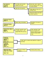
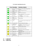
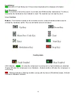
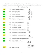
Page 7: ...7 Eiger Controller Fault Indicators 020 Tr Motor PTC Open High Motor Temperature...
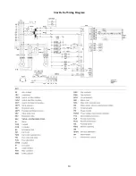
Page 14: ...14 Star Delta Wiring Diagram...
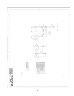
Page 15: ...15...
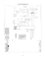
Page 16: ...16 Soft Start Wiring Diagram...
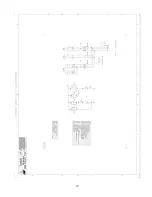
Page 17: ...17...
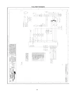
Page 18: ...18 Line Start Schematic...
Page 19: ...19...
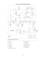
Page 20: ...20 Process and Instrumentation Diagram...
Page 21: ...21...
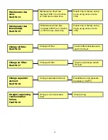
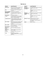
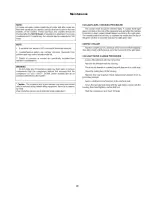
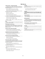
Page 28: ...28 Maintenance...
Page 29: ...29 Maintenance...
Page 30: ...30 Maintenance...
Page 31: ...31 S3 Controller Input Output Overview AI Analog Input DI Digital Input DO Digital Output...
Page 45: ...45 Standard S3 Menu Structure and Parameters Table 12...
Page 46: ...46 Standard S3 Menu Structure and Parameters Table 12...
Page 47: ...47 Standard S3 Menu Structure and Parameters Table 12...
Page 49: ...49 Modbus Register Listing...
Page 50: ...50 Table 13 Modbus Register Listing...
Page 52: ...52 Appendix 1 Thermistor 2ATT 34 to 124 C 255 F Air end Discharge...
Page 53: ...53...
Page 54: ...54...
Page 55: ...55...
Page 56: ...56...
Page 57: ...57...
Page 58: ...58 General Specifications for Eiger Packages...
Page 59: ...59...
Page 60: ...60...
Page 61: ...61...
Page 62: ...62...
Page 63: ...63...
Page 64: ...64...
Page 65: ...65...
Page 66: ...66...
Page 67: ...67...
Page 68: ...68...
Page 69: ...69...
Page 70: ...70...
Page 71: ...71...
Page 72: ...72...
Page 73: ...73...
Page 74: ...74...
Page 75: ...75...
Page 76: ...76...
Page 77: ...77...
Page 78: ...78...
Page 79: ...79...

