43
manually be re-started by any of the standard starting methods. Pressing the control panel start
button, or if Remote Control has been turned on, closing the Remote Start signal or sending a serial
start command.
ENH
Integral Sequencing
- It will be possible to sequence three Intellisys controllers without a
system controller. This is possible through a cable connecting, up to three Intellisys S3 controllers,
and using one of the controllers as a system controller.
MODULATION CONTROL OPTION
Modulation hardware extends the control types to Modulation (capacity control) and Automatic
Control System when the compressor switches between ’On/Off line’ and modulation as demand
varies. Safety of operation is provided for as the compressor will shut down if excessive
temperatures, electrical overload conditions, or system over pressure should occur.
For those plants which have relatively high constant air demand relative to the compressor capacity,
the recommended control mode is modulation. The modulation control system retains the features of
the on-line / off-line control, but also provides for throttling of the inlet flow up to the off-line air
pressure set point value. By applying line pressure to an adjustable modulator valve, the throttling
position of the inlet valve is controlled, thus allowing the modulator to ”trim” the inlet valve position as
dictated by the line pressure.
The modulating pressure range is about 0.3 bar (4.0 psid) and the modulator normally should be set
to straddle the compressor rated pressure. Modulation begins when the line pressure reaches about
99 percent of the compressor rated pressure and continues as/if the line pressure rises. Modulation
becomes stable when the compressor output equals the plant air demand. When the modulation is at
the factory setting, the maximum capacity reduction will be approximately 60 percent of the
compressor rated capacity (as indicated in Figure 1).
Summary of Contents for R110IU-10
Page 5: ...5 S3 Intellisys Controller Operating Instructions...
Page 6: ...6 Software Navigation...
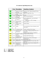
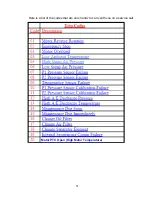
Page 7: ...7 Eiger Controller Fault Indicators 020 Tr Motor PTC Open High Motor Temperature...
Page 14: ...14 Star Delta Wiring Diagram...
Page 15: ...15...
Page 16: ...16 Soft Start Wiring Diagram...
Page 17: ...17...
Page 18: ...18 Line Start Schematic...
Page 19: ...19...
Page 20: ...20 Process and Instrumentation Diagram...
Page 21: ...21...
Page 28: ...28 Maintenance...
Page 29: ...29 Maintenance...
Page 30: ...30 Maintenance...
Page 31: ...31 S3 Controller Input Output Overview AI Analog Input DI Digital Input DO Digital Output...
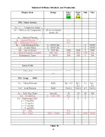
Page 45: ...45 Standard S3 Menu Structure and Parameters Table 12...
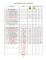
Page 46: ...46 Standard S3 Menu Structure and Parameters Table 12...
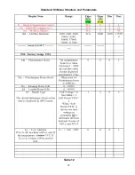
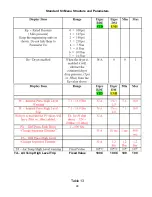
Page 47: ...47 Standard S3 Menu Structure and Parameters Table 12...
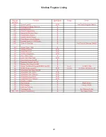
Page 49: ...49 Modbus Register Listing...
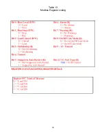
Page 50: ...50 Table 13 Modbus Register Listing...
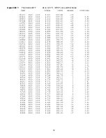
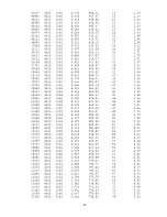
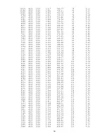
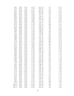
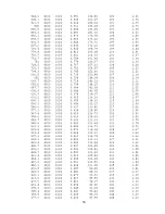
Page 52: ...52 Appendix 1 Thermistor 2ATT 34 to 124 C 255 F Air end Discharge...
Page 53: ...53...
Page 54: ...54...
Page 55: ...55...
Page 56: ...56...
Page 57: ...57...
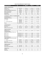
Page 58: ...58 General Specifications for Eiger Packages...
Page 59: ...59...
Page 60: ...60...
Page 61: ...61...
Page 62: ...62...
Page 63: ...63...
Page 64: ...64...
Page 65: ...65...
Page 66: ...66...
Page 67: ...67...
Page 68: ...68...
Page 69: ...69...
Page 70: ...70...
Page 71: ...71...
Page 72: ...72...
Page 73: ...73...
Page 74: ...74...
Page 75: ...75...
Page 76: ...76...
Page 77: ...77...
Page 78: ...78...
Page 79: ...79...

