44
MODULATE CONTROL VALVE ADJUSTMENT
Ensure that the compressor is isolated from the compressed air system by closing the isolation valve and
venting pressure from the drip leg. Ensure that the main power disconnect switch is locked open and tagged.
1. Put the compressor in the MODULATION mode.
2. Connect a pressure gauge to outlet port of modulation valve with 1/4” tubing tee.
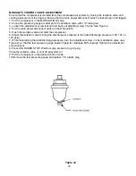
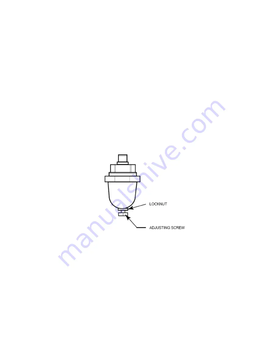
3. Loosen the adjustment screw locknut and back out adjusting screw 3 turns. See Figure 2
4. Put the main power disconnect switch in the ON position.
5. Open the isolation valve and start the compressor.
6. Adjust the isolation valve to bring the discharge air pressure to the rated discharge pressure (100, 125, or
140 psig).
7. While maintaining the rated discharge pressure, turn the adjustment screw on the modulation valve (see
Figure 2) so that the test pressure gauge reads:30 psig for modulate 60% capacity Tighten the adjustment
screw locknut.
8. Press UNLOADED STOP. Wait for sump pressure to go 0 psig.
Close the isolation valve or vent off all system air.
9. Put the compressor in the desired control mode.
10.Remove the test pressure gauge and replace 1/4” plastic plug.
Table 12
Summary of Contents for R110IU-10
Page 5: ...5 S3 Intellisys Controller Operating Instructions...
Page 6: ...6 Software Navigation...
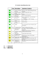
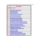
Page 7: ...7 Eiger Controller Fault Indicators 020 Tr Motor PTC Open High Motor Temperature...
Page 14: ...14 Star Delta Wiring Diagram...
Page 15: ...15...
Page 16: ...16 Soft Start Wiring Diagram...
Page 17: ...17...
Page 18: ...18 Line Start Schematic...
Page 19: ...19...
Page 20: ...20 Process and Instrumentation Diagram...
Page 21: ...21...
Page 28: ...28 Maintenance...
Page 29: ...29 Maintenance...
Page 30: ...30 Maintenance...
Page 31: ...31 S3 Controller Input Output Overview AI Analog Input DI Digital Input DO Digital Output...
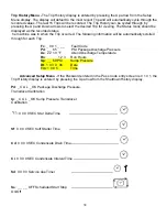
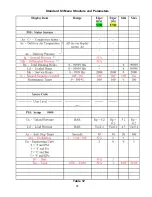
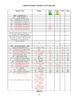
Page 45: ...45 Standard S3 Menu Structure and Parameters Table 12...
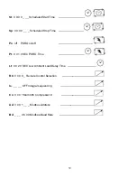
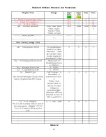
Page 46: ...46 Standard S3 Menu Structure and Parameters Table 12...
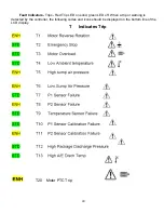
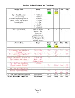
Page 47: ...47 Standard S3 Menu Structure and Parameters Table 12...
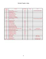
Page 49: ...49 Modbus Register Listing...
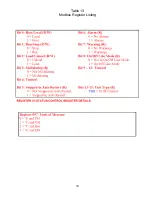
Page 50: ...50 Table 13 Modbus Register Listing...
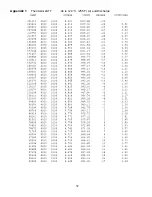
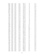
Page 52: ...52 Appendix 1 Thermistor 2ATT 34 to 124 C 255 F Air end Discharge...
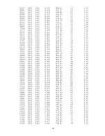
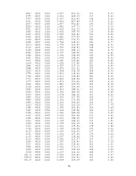
Page 53: ...53...
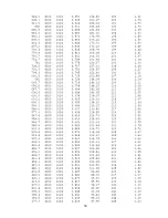
Page 54: ...54...
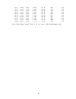
Page 55: ...55...
Page 56: ...56...
Page 57: ...57...
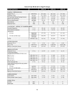
Page 58: ...58 General Specifications for Eiger Packages...
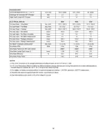
Page 59: ...59...
Page 60: ...60...
Page 61: ...61...
Page 62: ...62...
Page 63: ...63...
Page 64: ...64...
Page 65: ...65...
Page 66: ...66...
Page 67: ...67...
Page 68: ...68...
Page 69: ...69...
Page 70: ...70...
Page 71: ...71...
Page 72: ...72...
Page 73: ...73...
Page 74: ...74...
Page 75: ...75...
Page 76: ...76...
Page 77: ...77...
Page 78: ...78...
Page 79: ...79...

