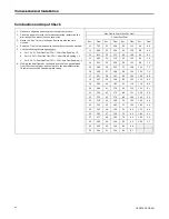
26
18-CE18D1-1B-EN
Special Case Venting
Special instructions for direct vent furnace air intake.
In certain applications, particularly when the furnace is located in a
basement, there are certain conditions that can be met where warm
humid air from the outside is drawn into combustion air piping. If the
area where the piping is located is conditioned below 70° F,
condensation could occur inside the piping and ultimately drain into
the furnace compartment, which could lead to premature component
failure.
We recommend following one of the options to prevent this condition
from occurring and possibly damaging components within the
furnace:
Note:
Inlet air piping is not considered to be part of the venting
system. The inlet air piping may be made from PVC.
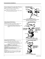
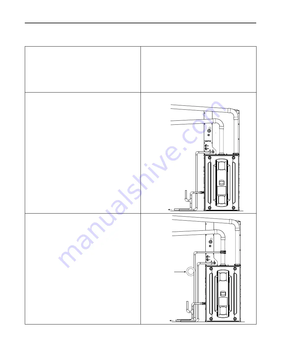
Option 1
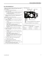
If possible, slope the inlet combustion air piping away from the
furnace. Condensation that may occur will now drain outside of the
home. The combustion air outlet piping must remain sloped back to
the furnace.
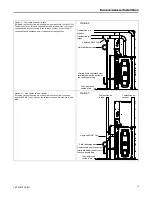
Option 1
Slope equals 1/4” per foot
To an approved
vented drain
Combustion air
intake
Combustion air
exhaust
Primary drain vent stack must
terminate below the bottom of
the condensate trap
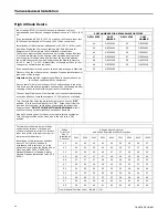
Optional In-line Condenser Trap Kit
The BAYCNDTRAP2 and BAYCNDTRAP3 may be used for Option 1
venting. The in-line condenser trap kit must be installed on the
vertical section of the combustion air intake pipe.
Note:
The in-line condenser trap may only be installed one way. See
the imprint on the trap to ensure the arrow is pointing towards
the furnace.
The BAYCNDTRAP2 is used when the system uses 2” vent pipe.
The BAYCNDTRAP3 is used when the system uses 3” vent pipe.
BAYCNDTRAP2
BAYCNDTRAP3
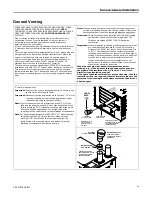
To an approved
vented drain
Combustion air
intake
Combustion air
exhaust
Field fabricated trap
Primary drain vent stack must
terminate below the bottom of
the condensate trap


