18-CE18D1-1B-EN
61
Condensate Drain Instructions
The following sections give general instructions for the
installation of the gas furnace condensate drains.
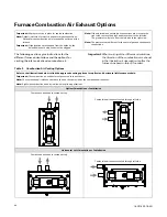
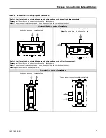
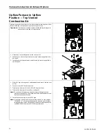
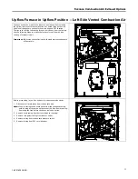
Repositioning of the condensate trap is covered in the
exhaust air options section.
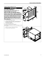
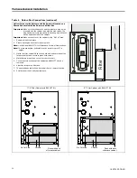
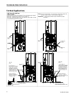
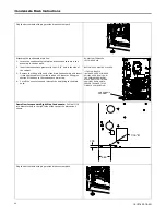
Cutouts with plugs and grommets are provided on the left and right
hand side of the furnace cabinets for drain connections
IN VERTICAL
APPLICATIONS
. The standard arrangement is for the drain connection
on the left side. The tubing may have to be trimmed in this application
to avoid kinking.
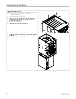
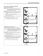
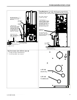
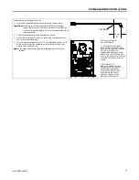
The
upflow (
vertical application
)
also has provisions for right side
drain connections. Exchange the grommet and plugs from the left and
right side. Trim all excess tubing to avoid kinking.
It is always recommended that an auxiliary drain pan be installed
under a horizontally installed evaporator or 90% Gas Furnace.
Connect the auxiliary drain line to a separate drain line (no trap is
needed in this line).
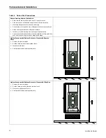
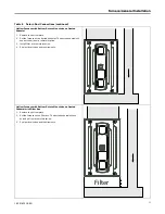
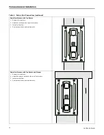
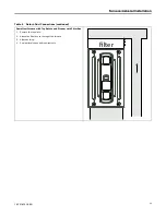
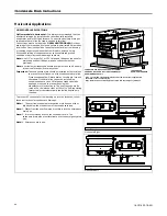
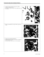
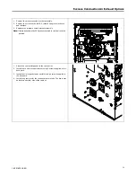
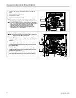
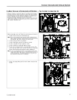
Horizontal applications require repositioning the condensate
canister trap. Additionally the drain tubing connected to the
inducer housing may need to be repositioned for removing the
plug and reconnecting the tubing to the lower connection on
the inducer housing.
Connections must be made to an
OPEN/ VENTED DRAIN
.
Note:
All condensate drain piping supplies included with the furnace
are intended for internal piping only and should not be applied
external to the furnace. All external piping must use 1/2"
minimum size PVC pipe and fittings throughout for drain
connections (fittings, pipe and PVC solvent cement not
provided with furnace, must be field supplied). A 3/4" coupling
is supplied to connect to systems that are using 3/4" piping
with an air conditioner coil.
Note:
A corrosion resistant condensate pump must be used if a pump
is required for a specific drain system.
C
CA
AU
UT
TIIO
ON
N
W
Wa
atte
err D
Da
am
ma
ag
ge
e//P
Prro
op
pe
errtty
y D
Da
am
ma
ag
ge
e!!
IItt iiss rre
ecco
om
mm
me
en
nd
de
ed
d tth
ha
att a
a d
drra
aiin
n p
pa
an
n b
be
e iin
nsstta
alllle
ed
d
u
un
nd
de
err tth
he
e ffu
urrn
na
acce
e tto
o p
prre
ev
ve
en
ntt p
prro
op
pe
errtty
y d
da
am
ma
ag
ge
e o
orr
p
pe
errsso
on
na
all iin
njju
urry
y ffrro
om
m lle
ea
akkiin
ng
g cco
on
nd
de
en
nssa
atte
e..
Important:
The condensate drain should be installed with provisions
to prevent winter freeze-up of the condensate drain line.
Frozen condensate will block drains, resulting in furnace
shutdown. If the drain line cannot be installed in a
conditioned space and/ or its surrounding ambient
temperature is expected to fall below freezing, then heat
tape should be applied as required to prevent freezing
(per manufacturer’s instructions). The heat tape should
be rated at 5 or 6 watts per foot at 120 volts. Self-
regulating (preferred) or thermostatically controlled heat
tape is required.
Typical sources of UL listed heat tapes are W.W. Granger, Inc.
(Wintergard PlusTM Series), McMaster Carr Supply Co. (3554 Series),
or your equipment supplier.
The condensate drain may be cleaned or inspected by removal of the
drain tube at the header.
Evaporator and Furnace condensate drain piping may be manifolded
together. A primary drain vent stack must be installed and terminated
below the outlet of the secondary heat exchanger drain connection to
prevent water from damaging Furnace controls if the primary drain
outlet plugs up.
Where the Furnace is installed above a finished ceiling, the
primary drain vent stack must be installed such that overflow
from the vent stack opening will flow into an auxiliary drain
pan in order to prevent water damage to the finished ceiling
below.

