18-CE18D1-1B-EN
9
Accessories
Table 1. Accessories
Model Number
Description
Use with
BAYHANG
Horizontal Hanging Kit
All Upflow Furnaces
BAYVENT200B
Sidewall Vent Termination Kit
All Furnaces
BAYVENTCN200B
Sidewall Vent Termination Kit (Canada —
CPVC)
All Furnaces
BAYAIR30AVENTA
Concentric Vent Kit
All Furnaces
BAYAIR30CNVENT
Concentric Vent Kit (Canada — CPVC)
All Furnaces
BAYREDUCE
Reducing Coupling (CPVC)
All Furnaces
BAYLIFTB
Dual Return Kit (B size extension)
B Cabinet Upflow Furnaces
BAYLIFTC
Dual Return Kit (C size extension)
C Cabinet Upflow Furnaces
BAYLIFTD
Dual Return Kit (D size extension)
D Cabinet Upflow Furnaces
BAYBASE205
Downflow Subbase
All Downflow Furnaces
BAYFLTR206
Filter Access Door Kit (Downflow only)
All Downflow Furnaces
BAYSF1165AA
(a)
1” SlimFit Box with MERV 4 Filter
All Upflow Furnaces
BAYLPSS400*
Propane Conversion Kit with Stainless Steel
Burners
All Furnaces
BAYMFGH200B
Manufactured/Mobile Housing Kit
All Furnaces
BAYCNDTRAP2A
Inline Condensate Trap Kit used with Special
Venting on 2” Vent Pipe
All Furnaces
BAYCNDTRAP3A
Inline Condensate Trap Kit used with Special
Venting on 3” Vent Pipe
All Furnaces
(a)
Airflow greater than 1600 CFM requires dual returns
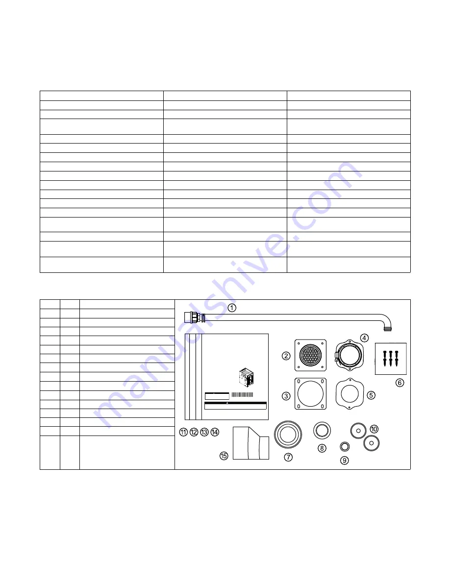
Document Pack Contents
Item
Qty.
Description
S
SA
AF
FE
ET
TY
Y W
WA
AR
RN
NIIN
NG
G
Only qualified personnel should install and service the equipment. The installation, starting up, and servicing of heating, ventilating, and air-conditioning
equipment can be hazardous and requires specific knowledge and training. Improperly installed, adjusted or altered equipment by an unqualified person
could result in death or serious injury. When working on the equipment, observe all precautions in the literature and on the tags, stickers, and labels that
are attached to the equipment.
February 2022
1
18
8--C
CE
E1
18
8D
D1
1--1
1B
B--E
EN
N
Upflow/Horizontal and Dedicated Downflow
Gas-Fired, Direct/Non-Direct Vent, 2–Stage
Condensing Variable Speed Furnaces
U
Up
pffllo
ow
w,, C
Co
on
nv
ve
errttiib
blle
e tto
o
H
Ho
orriizzo
on
ntta
all R
Riig
gh
htt o
orr
H
Ho
orriizzo
on
ntta
all L
Le
efftt
S9V2B040U3PSBC/D
S9V2B060U4PSBC/D
S9V2B080U4PSBC/D
S9V2C080U5PSBC/D
S9V2C100U5PSBC/D
S9V2D120U5PSBC/D
D
Do
ow
wn
nffllo
ow
w O
On
nlly
y
S9V2B040D3PSBC/D
S9V2B060D3PSBC/D
S9V2B080D4PSBC/D
S9V2C100D5PSBC/D
S9V2D120D5PSBC/D
N
No
otte
e
:: Graphics in this document are for
representation
only. Actual
model may differ in appearance.
▲
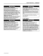
CAUTION
!
COIL REQUIREMENT!
Failure
to follow this Caution could result in property damage or personal injury. 4GXC* and
4MXC* coils installed on upflow furnaces in vertical, horizontal left, or horizontal right
orientations without a factory installed metal drain pan shield must use a MAY*FERCOLKITAA
kit. Coils installed on upflow furnaces must have drain pans that are suitable for 400° F
(205°C) or have a metal drain pan shield. Downflow furnaces do not require a metal drain pan
shield or the use of the MAY*FERCOLKITAA kit. See Installer’s Guide for more information.
18-CE18D1-1B-EN
Installer’s Guide
1
1
Condensate Drain Tube Assembly
2
1
Inlet Vent
(a)
3
1
Inlet Vent Gasket
4
1
Outlet Vent Assembly
5
1
Outlet Vent Gasket
6
6
Screws
7
1
Condensate Trap Grommet
8
1
Plug — Condensate/Gas
9
1
Plug — Electrical
10
2
Grommet — Condensate/Gas
11
1
Installer’s Guide
12
1
Service Facts
13
1
Owner Guide
14
1
Limited Warranty
15
1
2” to 3” Coupling — CPL00938
(b)
(a)
3” inlet vent supplied with S9V2D120U5PS and S9V2D120D5PS only. 2” inlet vent supplied with all other models.
(b)
Supplied with S9V2D120U5PS and S9V2D120D5PS only.


