background image

http://air.ingersollrand.com 

1

OPeRATIOn AnD MAInTenAnCe MAnUAL 

InSTALLATIOn / HAnDLInG

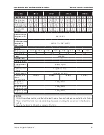
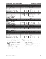
60Hz

UP6 5 

UP6 7

UP6 10

UP6 15c


COMPReSSOR

125

150

210

125

150

210

125

150

210

125

150

210

Operating pres-

sure PSIG (bar)

125 

(.)

150 

(10.)

-- 

125 

(.)

150 

(10.)

210 

(1.5)

125 

(.)

150 

(10.)

210 

(1.5)

125 

(.)

150 

(10.)

210 

(1.5)

Factory set reload 

pressure PSIG (bar)

110 

(.5)

10 

(.)

--

110 

(.5)

10 

(.)

10 

(12.1)

110 

(.5)

10 

(.)

10 

(12.1)

110 

(.5)

10 

(.)

10 

(12.1)

Flow rate CFM 

(m

/MIN)

1.5 

(0.52)

1.0 

(0.5)

 --

2.0 

(0.)

25.0 

(0.1)

1.5 

(0.50)

.0 

(1.0)


(0.)

2.0 

(0.)

55.0 

(1.55)

50.0 

(1.2)

.0 

(1.0)


Airend discharge 

temperature trip 

point.

22°F (10°C)

Ambient operating 

temperature

(min.) 

(max.)

°F (+2°C) 

 105°F (+0°C)


MOTOR

Motor enclosure

ODP

TEFC

ODP

TEFC

ODP

TEFC

ODP

TEFC

Nominal power

5HP

.5HP

10HP

15HP

Speed

                                                                                       500 RPM

Insulation class

                                                                                                 F


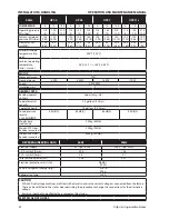
GeneRAL DATA

Residual coolant 

content

ppm ( mg/m

)

Separator vessel 

capacity

0. gallons ( Litres)

Coolant capacity

1.2 gallons (.5 Litres)

Sound pressure 

level to 

CAGI-PNEUROP

5 dB(A)

5 dB(A)

 dB(A)

 dB(A)

Weight-base 

mount unit

25kg (50lb)

Weight-0 gallon 

Receiver mounted

20kg (25lb)

Weight-120 gallon 

Receiver mounted

kg (0lb)


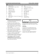
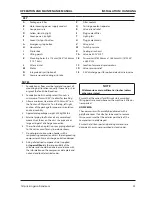
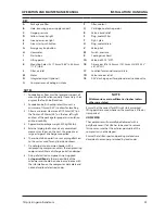
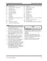
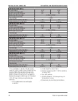
CAUTIOn

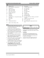
20/0 Dual voltage machines are fitted with a decal to advise the correct voltage as connected from the factory.
There is a decal fitted to the starter door describing the procedure to change the connections for the alternative 

voltage. 
Rewiring should only be effected by a competent Electrician.


Summary of Contents for SSR UP5-11c

Page 1: ... SSR UP6 5 UP6 7 5 UP6 10 UP6 15c 60 Hz OPERATION AND MAINTENANCE MANUAL This manual contains important safety information and must be made available to personnel who operate and maintain this machine Refer all communications to the nearest Ingersoll Rand Full Service Distributor ...

Page 2: ...mpany Accessories or equipment furnished by the Company but manufac tured by others shall carry whatever warranty the manufacturers have conveyed to the Company and which can be passed on to the Purchaser The Company shall not be liable for any repairs replacements or adjustments to the Equipment or any costs of labor performed by the Purchaser or others without Company s prior written approval Th...

Page 3: ...P6 5 15HP SD 3PH 60Hz 16 SCHEMATIC ELECTRICAL UP6 5 15HP FV 1PH 60Hz U S A 17 SCHEMATIC ELECTRICAL UP5 5 15HP FV 3PH 50Hz DOL 18 SCHEMATIC ELECTRICAL UP5 5 15HP SD 3PH 50Hz 19 installation handling 20 UNPACKING 21 UP SERIES TANK MOUNTED 80 GAL 22 UP SERIES TANK MOUNTED 120 GAL 24 UP SERIES TANK MOUNTED 272 LITRES 26 UP SERIES TANK MOUNTED 500 LITRES 28 LOCATION IN THE PLANT 30 DISCHARGE PIPING 30 ...

Page 4: ...ANCE 43 MOISTURE SEPARATOR MAINTENANCE 44 AIR FILTER MAINTENANCE 44 DISASSEMBLING THE UNIT 45 REFRIGERANT LEAKS IN THE REFRIGERATION CIRCUIT 45 REFRIGERANT CHARGING 45 CHARACTERISTICS OF REFRIGERANT R134A 45 TROUBLESHOOTING 45 MAINTENANCE 45 TROUBLE SHOOTING 46 ABBREVIATIONS SYMBOLS Contact Ingersoll Rand for serial number Up to Serial No From Serial No Not illustrated Option NR Not required AR As...

Page 5: ...and has no control Therefore Ingersoll Rand does not accept any liability for losses caused by equipment in which non approved repair parts are installed Standard warranty conditions may be affected Ingersoll Rand reserves the right to make changes and improvements to products without notice and without incurring any obligation to make such changes or add such improvements to products sold previou...

Page 6: ...RNING Pressurised component or system WARNING Air gas flow or Air discharge Do not breathe the compressed air from this machine Use fork lift truck from this side only RESET Do not use fork lift truck from this side Off power On power Emergency Stop Read the Operation and Maintenance manual before operation or maintenance of this machine is undertaken Do not operate the machine without the guard b...

Page 7: ...http air ingersollrand com OPERATION AND MAINTENANCE MANUAL DECALS ...

Page 8: ... vapors which can result in serious injury Never operate the compressor near flammable liquids or vapors If used to spray flammable materials keep compressor at least 20ft 6m away from the spray area HIGH PRESSURE AIR Rusted tanks can cause explosion and severe injury or death Receiver under pressure Operator should relieve tank pressure before performing maintenance In addition to automatic drain...

Page 9: ... Dryer packages only 5 92960593 2 Decal warning hazardous 14 22459200 1 Tag rotation voltage 15 SPEC 1 Specifications compressor 6 93166478 1 Decal condensate drain package 7 22530331 1 Decal dryer bypass instruction 16 93166486 1 Decal power inlet 8 23353196 1 Decal maintenance parts 17 22141311 1 Decal place to cover hole 9 92930585 1 Decal pressurized vessel 18 22604276 1 Decal multiple wiring ...

Page 10: ...ecal wiring schematic diagram 22529291 1 Decal facia Round hourmeter 22 93171262 1 Decal lift here both sides Base mount only 26 23038474 1 Decal Ingersoll Rand logo 23 22913032 1 Decal Ingersoll Rand logo Base mount only 27 22454060 1 Decal belt 22435713 1 Decal Ingersoll Rand logo Receiver mount only 28 Tank mount option 24 92930668 1 Decal no maintenance before referring to manual 29 54618681 1...

Page 11: ...of plastic bowls on line filters can be hazardous Their safety can be affected by either synthetic lubricants or the additives used in mineral oils Ingersoll Rand recommends that only filters with metal bowls should be used on a pressurised system Compressed air Compressed air can be dangerous if incorrectly handled Before doing any work on the unit ensure that all pressure is vented from the syst...

Page 12: ... from exposed live parts of the compressor electrical system Maintain dry footing stand on insulating surfaces and do not contact any other portion of the compressor when making adjustments or repairs to exposed live parts of the compressor electrical system WARNING Any electrical connections or adjustments should only be made by a suitably qualified electrician Close and lock all access doors whe...

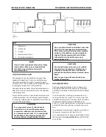
Page 13: ...http air ingersollrand com 13 OPERATION AND MAINTENANCE MANUAL GENERAL INFORMATION General information PIPING AND INSTRUMENTATION 22426035 REV F ...

Page 14: ...7 Tank separator fine 27 Valve isolation option 8 Valve minimum pressure 28 Moisture separator 9 Aftercooler 29 Valve check 10 Valve blowdown 30 Evaporator 11 Switch pressure 31 Indicator dew point 12 Switch temperature 32 Valve condensate 13 Filter coolant 33 Tube capillary 14 Thermostat 34 Filter drier refrigerant 15 Cooler oil 35 Condenser 16 Valve pilot 36 Valve hot gas bypass 17 Valve relief ...

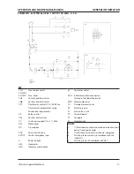
Page 15: ...mer nameplate for wiring connection requirements OL Overload motor starter CR Relay control PS Switch pressure CRa Contact control relay ST Push button start CS Customer supplied 115v 1 60hz TP Terminal points DO Dryer option TS To supply DM Motor dryer W Standby light EDV Valve electric drain 120 1 50 60 NOTES E STOP Button emergency stop 1 Furnished mounted and wired outside of control panel if ...

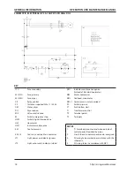
Page 16: ...tor OLa Contact main motor overload 2M Contactor delta PS Switch pressure 2Ma b Contacts auxiliary Delta contactor ST Push button start 1S Contactor star T D Relay delta starting 10sec 1Sa b Contacts auxiliary Star contactor TDc Relay delay off contact 1SV Valve solenoid nc CPT Transformer control NOTES CR Relay control 1 Furnished mounted and wired outside of control panel if required by order CR...

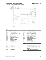
Page 17: ...motor starter Transformer nameplate for wiring PS Switch pressure Connection requirements ST Push button start CR Relay control TP Terminal points CRa Contact control relay TS To supply CS Customer supplied 115v 1 60hz W Standby light DM Motor dryer NOTES DO Dryer option 1 Furnished mounted and wired outside of control panel if required by order EDV Valve electric drain 2 Circuit shown in normal p...

Page 18: ...ssure DM Motor dryer ST Push button start DO Dryer option T1 Transformer control EDV Valve electric drain TP Terminal points ES Switch emergency stop TS To supply HATS Switch high air temperature HM Hourmeter HM1 Indicator maintenance NOTES KM Contactor main 1 Furnished mounted and wired outside of control panel if required by order KM 1 2 Contacts auxiliary Main contactor 2 Circuit shown in norma...

Page 19: ...nstead of standard hourmeter HATS Switch high air temperature MOL Overload main motor HM Hourmeter MOL 1 Contact main motor overload HM1 Indicator maintenance ST Push button start MM Motor compressor T1 Transformer control P Switch pressure TM1 Relay delta starting 10sec ES Switch emergency stop TM1 1 Relay delay off contact FU1 FU2 Fuse primary FU3 Fuse secondary NOTES FU4 FU5 Fuse dryer 1 Furnis...

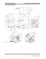
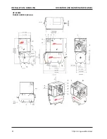
Page 20: ...http air ingersollrand com INSTALLATION HANDLING OPERATION AND MAINTENANCE MANUAL installation handling WITH OPTIONAL OUTDOOR MOD WITH OPTIONAL OUTDOOR MOD ROTATION VIEW TOP VIEW LEFT VIEW RIGHT VIEW FRONT ...

Page 21: ...roper air circulation and serviceability 4 Approximate package weight 298kg 655lbs 5 External piping shall not exert any unresolved moments or forces on the unit Use pipe size as large or larger at discharge connection 6 There should be no plastic or pvc piping attached to this unit or used for any lines downstream 7 Do not pipe into a common header with a reciprocating compressor unless the recip...

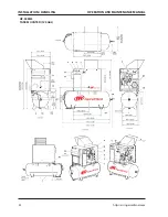
Page 22: ...22 http air ingersollrand com INSTALLATION HANDLING OPERATION AND MAINTENANCE MANUAL UP SERIES TANK MOUNTED 80 GAL ...

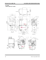
Page 23: ...inimum clearance of 1100mm 42 on the front and 920mm 36 on the top left right and rear of the package for proper air circulation and serviceability 4 Approximate package weight 420kg 925lbs 5 External piping shall not exert any unresolved moments or forces on the unit Use pipe size as large or larger at discharge connection 6 There should be no plastic or pvc piping attached to this unit or used f...

Page 24: ...24 http air ingersollrand com INSTALLATION HANDLING OPERATION AND MAINTENANCE MANUAL UP SERIES TANK MOUNTED 120 GAL ...

Page 25: ...inimum clearance of 1100mm 42 on the front and 920mm 36 on the top left right and rear of the package for proper air circulation and serviceability 4 Approximate package weight 430kg 946lbs 5 External piping shall not exert any unresolved moments or forces on the unit Use pipe size as large or larger at discharge connection 6 There should be no plastic or pvc piping attached to this unit or used f...

Page 26: ...26 http air ingersollrand com INSTALLATION HANDLING OPERATION AND MAINTENANCE MANUAL UP SERIES TANK MOUNTED 272 LITRES ...

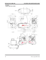
Page 27: ...inimum clearance of 1100mm 42 on the front and 920mm 36 on the top left right and rear of the package for proper air circulation and serviceability 4 Approximate package weight 400kg 880lbs 5 External piping shall not exert any unresolved moments or forces on the unit Use pipe size as large or larger at discharge connection 6 There should be no plastic or pvc piping attached to this unit or used f...

Page 28: ...28 http air ingersollrand com INSTALLATION HANDLING OPERATION AND MAINTENANCE MANUAL UP SERIES TANK MOUNTED 500 LITRES ...

Page 29: ...inimum clearance of 1100mm 42 on the front and 920mm 36 on the top left right and rear of the package for proper air circulation and serviceability 4 Approximate package weight 455kg 1000lbs 5 External piping shall not exert any unresolved moments or forces on the unit Use pipe size as large or larger at discharge connection 6 There should be no plastic or pvc piping attached to this unit or used ...

Page 30: ...ver using individual air lines CAUTION The use of plastic bowls on line filters and other plastic air line components can be hazardous Their safety can be affected by either synthetic coolants or the additives used in mineral oils Ingersoll Rand recommends that only filters with metal bowls should be used on any pressurised system CAUTION The standard compressor unit is not suitable for operation ...

Page 31: ...mbient operating temperature min max 36 F 2 C 105 F 40 C MOTOR Motor enclosure ODP TEFC ODP TEFC ODP TEFC ODP TEFC Nominal power 5HP 7 5HP 10HP 15HP Speed 3500 RPM Insulation class F GENERAL DATA Residual coolant content 3ppm 3 mg m3 Separator vessel capacity 0 8 gallons 3 Litres Coolant capacity 1 2 gallons 4 5 Litres Sound pressure level to CAGI PNEUROP 65 dB A 65 dB A 68 dB A 69 dB A Weight bas...

Page 32: ...s F GENERAL DATA Residual coolant content 3ppm 3 mg m3 Separator vessel capacity 0 8 gallons 3 Litres Coolant capacity 1 2 gallons 4 5 Litres Sound pressure level to CAGI PNEUROP 65 dB A 65 dB A 68 dB A 69 dB A Weight base mount unit 295kg 650lb Weight 272 Litres Receiver mounted 420kg 925lb Weight 500 Litres Receiver mounted 454kg 1000lb DRYER ENGINEERING DATA 60Hz 50Hz Electrical supply 115V 1ph...

Page 33: ...Sec 7 10 Sec Starts per hour maximum 6 Control voltage 120VAC Recommended fuse rating See note 1 50A 45A 20A 15A Recommended wire size AWG See note 2 8 8 12 14 ELECTRICAL DATA UP6 15c Standard voltage 230V 1PH 200V 230V 3PH 460V 575V Full load current maximum 43 2A 37 6A 18 8A 15 1A Starting current DOL Star Delta Starting time DOL Star Delta 3 5 Sec 7 10 Sec Starts per hour maximum 6 Control volt...

Page 34: ...our maximum 6 Control voltage 120VAC Recommended fuse rating See note 1 20A 20A Recommended wire size See note 2 4 mm 2 Cu 4 mm2 Cu ELECTRICAL DATA UP5 11c Standard voltage 380V 400V Full load current maximum 23 0A 21 9A Starting current DOL Star Delta 79 75 Starting time DOL Star Delta 3 5 Sec 7 10 Sec Starts per hour maximum 6 Control voltage 120VAC Recommended fuse rating See note 1 32A 32A Rec...

Page 35: ... equipment The length of wiring from a suitable electrical feed point is critical as voltage drops may impair the performance of the compressor Feeder cables wires connections to isolator or disconnect should be tight and clean The applied voltage must be compatible with the motor and compressor data plate ratings The control circuit transformer has different voltage tappings Ensure that these are...

Page 36: ...ontained in the air is condensed and may be drained from the downstream piping and equipment The coolant system consists of a sump cooler thermostatic valve and a filter When the unit is operating the coolant is pressurized and forced to the compressor bearings The compressor load control system is automatic on off line This allows the compressor to maintain a set discharge line pressure by varyin...

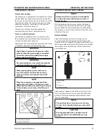
Page 37: ...on note When the compressor is equipped with the optional dryer and filters the pressure switch differential should be increased 10psi to account for the added pressure drop of the filters and dryer A Upper Pressure Setting B Pressure Differential AUTOMATIC START STOP CONTROL NOTE Automatic Start Stop Control is intended for use when the motor will start no more than 6 times per hour When the rece...

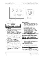
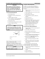
Page 38: ...n as the demand for air returns 7 DEW POINT INDICATOR Dryer Option Green indicates good dew point Red indicates ew point above 50 F 10 C Blue indicates freezing PRIOR TO STARTING 1 Make visual check of the machine ensure that all guards secure and that nothing is obstructing the proper ventilation of or free access to the machine 2 Check coolant level Add if necessary 3 Make sure air discharge val...

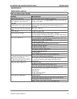
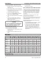
Page 39: ... in IRGP and IRHE filters Change the coolant filter Check scavenge screen for blockage clean if required Change the separator element Change the Air Filter element Take coolant sample for fluid analysis Change the package pre filter Check Drive Belts Motors without grease fittings Replace sealed bearings 1 year external and 6 years internal pressure vessel inspection Frequency may be otherwise def...

Page 40: ...tic blowdown valve is used for this purpose then allow enough time for it to complete the operation the machine cannot be started accidentally or otherwise all residual electrical power sources mains and battery are isolated Prior to opening or removing panels or covers to work inside a machine ensure that anyone entering the machine is aware of the reduced level of protection and the additional h...

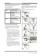
Page 41: ...fter the compressor has been operating as the liquid will drain more easily and any contaminant will still be in suspension Stop the machine electrically isolate and vent all trapped pressure Place a suitable container close to the drain valve Slowly remove fill cap Remove plug from drain valve Open the drain valve and drain coolant into container Close the drain valve Replace plug in drain valve ...

Page 42: ...evident the belt is usually adjusted satisfactorily A belt tension measurement device can be used to determine the tension of the belt Belt tensioning can be achieved by loosening the airend anchor screws a belt tensioning bolt is provided to aid in moving the airend Follow the procedures outlined below to correctly set and measure belt tension 1 Lay a straight edge across the top outer surface of...

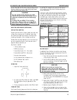
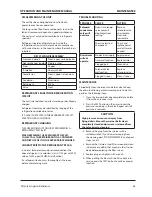
Page 43: ...or drains condensate The timer s cycle rate and drain opening time should be adjusted to open just long enough to discharge the condensate The timer is properly set when it opens and discharges condensate and then vents air for approximately one second before closing Adjustments may be made depending on many factors including humidity and duty cycle TROUBLESHOOTING TROUBLE CAUSE ACTION Valve will ...

Page 44: ...using from the air supply Fully depressurize in drain bowl as appropriate Unscrew bowl and remove If pressure has not been completely released from the housing air will escape from the warning hole giving an audible alarm Screw back bowl and repeat instruction 2 before attempting again Should resistance to unscrewing be experienced provision is made for a C spanner to fit onto the ribs of the bowl...

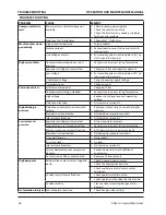
Page 45: ... gas with TVL value of 1000 ppm ASHRAE classification If a refrigerant leak occurs thoroughly air the room before commencing work TROUBLESHOOTING TROUBLE CAUSE ACTION Solenoid condensate valve will not close Debris in solenoid valve prevents diaphragm from seating Remove solenoid valve disassemble clean and reassemble Short in electrical component Check and replace power cord or timer as needed Dr...

Page 46: ...ge to correct operating voltage Defective inlet valve Fit inlet valve service kit High discharge pressure Defective or incorrect pressure switch setting Replace or set pressure to correct rating for machine Blowdown valve defective Fit blowdown solenoid service kit Inlet valve malfunction Fit inlet valve service kit Low system air pressure Separator cartridge contaminated Fit new Separator element...

Page 47: ...ure switch setting Replace or set pressure to correct rating for machine Minimum pressure valve malfunction Fit Minimum pressure valve service kit Blowdown valve defective Fit blowdown solenoid service kit Inlet valve malfunction Fit inlet valve service kit Pressure relief valve defective Check the setting of the pressure relief valve and the rated pressure Black residue on belt guard cooler box D...

Page 48: ... overhaul your equipment to factory specifications using only genuine Ingersoll Rand parts A SUBSTITUTE IS NOT A REPLACEMENT Ensure you get peak performance and longevity out of your Ingersoll Rand product by insisting on genuine Ingersoll Rand replacement parts and maintenance kits Not only are the replacement parts made to precise dimensions and OEM specified metallurgy but each part is backed b...

Reviews: