34
18-GJ83D1-1C-EN
7.
Secure the sheathed wiring to the control pocket mounting plate using the factory supplied wire ties attached to the tabs as shown.
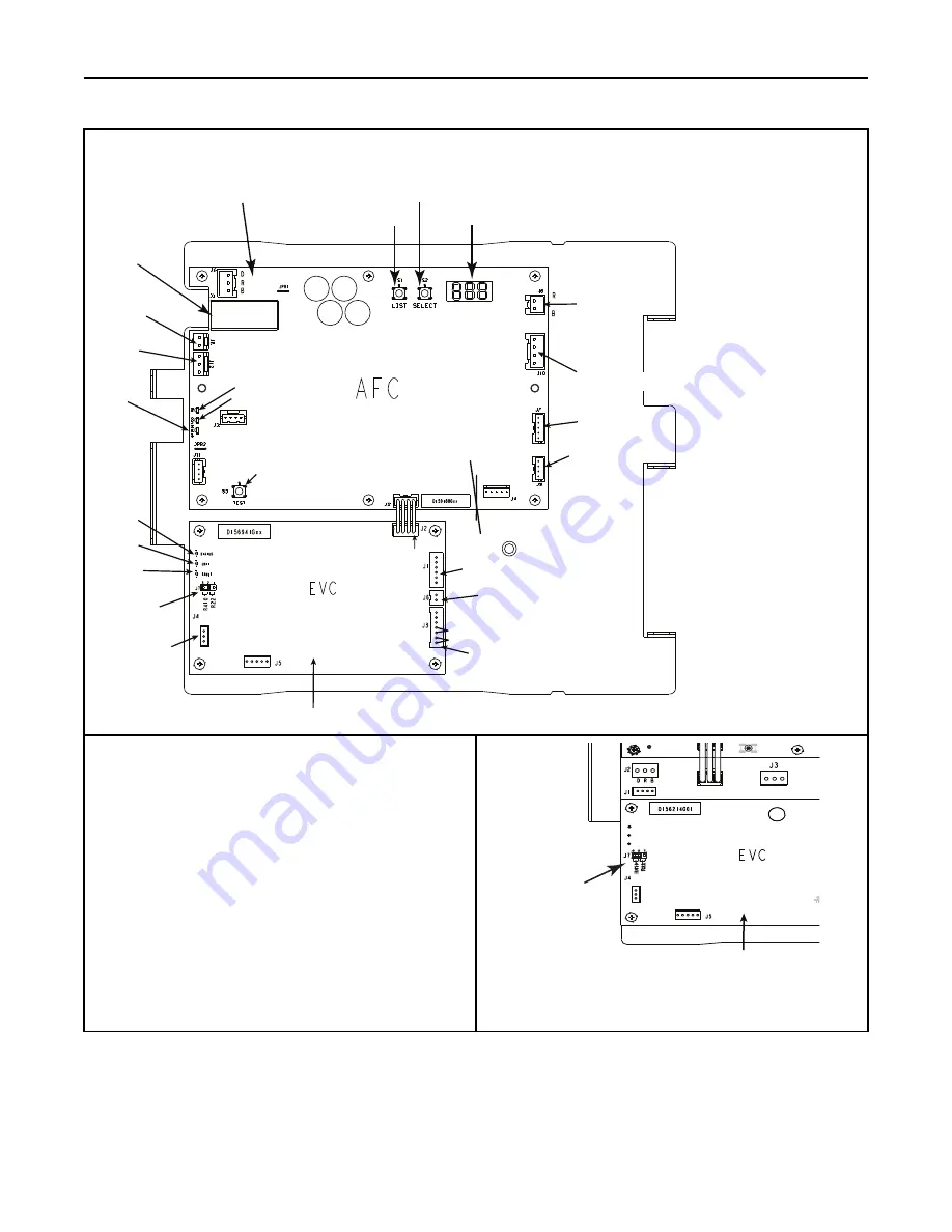
SELECT Button
7 Segment Display
LIST Button
Electronic Expansion Valve Control (EVC)
Airflow Control (AFC)
J10 -
EHC/HHC
J7
R410A / R22
J4
OPEN
TEST
CLOSE
STATUS
LED
BM LED
COMM LED
Unit Test
J3
J6
J1
To EEV Stator
To Internal
Condensate Switch
(Optional)
GT Sensor
ET Sensor
J2
13.8 VDC
Distribution
Board
J7 - Motor
J8 - 24 VAC Input
J9 - Display Assembly
J5
External Switch
J12
Humidifier
Low Voltage
thermostat
harness
STATUS
LED
FAULT
LED
UNIT
LED
8.
Set Jumper and Dip Switches
•
Set the system refrigerant to either R410A or R-22 using the
Refrigerant Jumper located on the Expansion Valve Control board
(EVC) in the Control Pocket.
•
Factory default is R410A.
Note:
The power must be shut off and then re-applied in order for the
EVC to recognize the change.
2
1
R
2
2
3
R
4
1
0
J7 Jumper
GAS
TEMP
GAS
TEMP
Electronic Expansion Valve Control (EVC)
TEST
CLOSE
OPEN
TEST
24 VAC
FAULT
UNIT
STATUS
D
1
5
6
2
31
H


