Unit Description
25
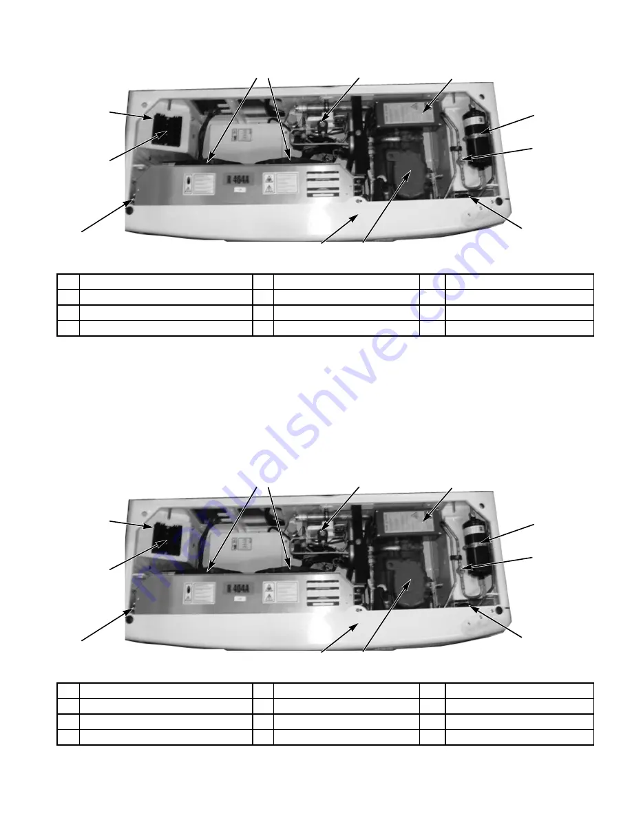
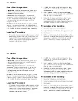
Figure 10: Unit Components (Model 20)
1
6
11
AMA1412
2
4
5
7
8
9
10
3
1.
Filter-Drier
5.
Oil Separator (under cover)
9.
Transformer Cover
2.
Liquid Sight Glass
6.
Electric Standby Compressor
10.
Condenser Fans
3.
Liquid Injection Valve
7.
Condenser Coil
11.
AC Compressor Electric Box
4.
Liquid Tank (?)
8.
Rectifier Heat Sink
Summary of Contents for Thermo King V-520 10
Page 2: ......
Page 4: ...2 2...
Page 6: ...Introduction 4 Introduction 4...
Page 14: ...Safety Precautions 14 Safety Precautions 14...
Page 40: ...Unit Operation 40 Unit Operation 40...
Page 48: ...Specifications 48 Specifications 48...
Page 52: ...Maintenance Inspection Schedule 52 Maintenance Inspection Schedule 52...
Page 58: ...Loading and Enroute Inspections 58 Loading and Enroute Inspections 58...
Page 60: ...Serial Number Locations 60 Serial Number Locations 60...
Page 62: ...Warranty 62 Warranty 62...
Page 72: ...72 72...
Page 73: ......


